Field-Oriented Control (FOC) of PMSM Using Hardware-in-the-Loop (HIL) Simulation
This example uses hardware-in-the-loop (HIL) simulation to implement the field-oriented control (FOC) algorithm to control the speed of a three-phase permanent magnet synchronous motor (PMSM). The FOC algorithm requires rotor position feedback, which is obtained by a quadrature encoder sensor. For more information on FOC, see Field-Oriented Control.
NOTE: This example runs only on Windows® and Linux® platforms. It is not supported on the Mac platform.
When the actual motor and inverter hardware are not available, you can use the HIL simulation workflow to validate the FOC algorithm in real-time by operating a realistic virtual plant. The HIL simulation setup consists of these elements:
Desktop computer or development hardware running Simulink®
Controller hardware running the code for the controller
Target hardware (FPGA) running the code for the physical plant
You need to deploy the controller code to the controller hardware and the HDL code for the plant to the FPGA target hardware. After deploying the controller code, the controller runs the FOC algorithm and outputs actual PWM signals. Whereas, after HDL code deployment, the FPGA hardware effectively emulates the actual inverter and motor by running the HDL code for the plant. Therefore, it replicates the actual plant by accepting the PWM signals and providing realistic current and rotor position feedback to the controller in real-time. The FPGA hardware runs in external mode and logs data in the Simulation Data Inspector of the Simulink Real-Time™ model.
The Simulink host model running on the desktop computer, interacts with the controller using serial communication protocol. You can use the host model to communicate with the controller, and therefore, control the motor operation.

You can also use this setup to effectively test scenarios like hardware failures, motor burn-out, and other faults. To know more about HIL simulation, see .
Open MATLAB Project
The example is packaged as a MATLAB® project. Use one of these methods to open the MATLAB project window:
1. Click Open Project.
2. Run the following command to access the supporting files of the example and open the MATLAB project.
openExample('mcb/FieldOrientedControlOfPMSMUsingHardwareInTheLoopHILExample');
Model
The MATLAB project has a model folder that includes the following models:
mcb_pmsm_foc_f28379d.slx- This target model contains the FOC algorithm that you can deploy and run on the controller hardware. The model algorithm applies theSubcycle Averagingmethod for simulation and to run on the controller hardware to validate the controller FOC algorithm. You can use this model to generate the embedded C code for the controller hardware.

mcb_host_f28379d.slx- This is a host model to communicate with the embedded target hardware. Using this model, you can start the simulation and run the motor. You can then generate PWM signals and log data from controller hardware using this model.

Apart from these two models, you will need an FPGA plant model (a combination of inverter and motor equations), which you can deploy and run on the FPGA target hardware, and a Simulink Real-Time application model, which you can use to choose the target hardware and deploy the FPGA plant model algorithms. This example provides the default FPGA plant model slrt_ex_pmsm.slx and the default Simulink Real-Time application model slrt_ex_pmsm_gm.slx for the supported target hardware configuration.
The FPGA plant model captures the PWM duty cycles provided by the controller and, in turn, runs the inverter and motor equations to generate and send back the actual ADC voltage and position signals to the controller hardware.
If you want to use the default FPGA plant model with the default hardware configuration supported by the example, you can directly use the following files to deploy the FPGA plant model algorithms and program the FPGA hardware:
Default Simulink Real-Time application model
slrt_ex_pmsm_gm.slx.
Default FPGA hardware bitstream file. To download the default bitstream file for the hardware configuration supported by the example, see Power Electronics Templates for Simulink Real-Time.
However, if you modify the FPGA plant model or use a different FPGA plant model for a different hardware configuration, you must use HDL Workflow Advisor to regenerate the following files from the modified or new FPGA plant model:
Simulink Real-Time application model.
FPGA hardware bitstream file.
You can then use these two files to deploy the FPGA plant model algorithms and program the FPGA hardware. For more details about generating these two files using HDL Workflow Advisor, see Getting Started with the HDL Workflow Advisor (HDL Coder).
Required MathWorks Products
To simulate model:
Motor Control Blockset™
To generate code and deploy model:
1. Motor Control Blockset
2. Simulink Real-Time
3. Embedded Coder®
4. C2000™ Microcontroller Blockset
5. Fixed-Point Designer™ (only needed for optimized code generation)
6. Stateflow®
7. HDL Coder™ (only needed if you change the FPGA plant model or the hardware configuration)
8. Speedgoat® I/O Blockset
Prerequisites
1. Obtain the motor and inverter parameters. The MATLAB project uses default motor and inverter parameters that you can replace with values from either the motor and inverter datasheets or from other sources.
Optionally, if you have the actual motor, you can estimate the parameters for the motor that you want to use with the motor control hardware by using the Motor Control Blockset parameter estimation tool. For instructions, see Estimate Motor Parameters Using Motor Control Blockset Parameter Estimation Tool. The parameter estimation tool updates the motorParam variable (in the MATLAB workspace) with the estimated motor parameters.
2. Update the motor and inverter parameters in the mcb_pmsm_foc_f28379d_data.m parameter script associated with the target models available in the MATLAB project. This script automatically opens when you open the MATLAB project. You can also use the Project window to open this script from the scripts folder.
3. Click Run on the Editor tab to run the parameter script.
Simulate Model
Follow these steps to simulate the models included in the project:
1. Open target model mcb_pmsm_foc_f28379d.slx from the model folder included in the MATLAB project.
2. Click Run on the Simulation tab to validate the motor operation. You can increase the simulation speed by reducing the FPGA frequency f_base to 2MHz in pmsm_hil_data.m script. Observe the simulation results. Make sure to revert f_base to 200MHz before deploying to FPFA hardware.
3. Open FPGA plant model slrt_ex_pmsm.slx. If you want to change the FPGA plant model, update slrt_ex_pmsm.slx. Simulate mcb_pmsm_foc_f28379d.slx to verify the changes in simulation.
Generate Code and Deploy Model to Target Hardware
This section shows you how to generate code and run the FOC and plant model algorithms on the controller and FPGA target hardware.
In addition to the target model, the MATLAB project uses a host model. The host model, which is a user interface to the controller hardware board, runs on the host desktop computer. To use the host model, you need to deploy the target model mcb_pmsm_foc_f28379d.slx to the controller hardware board. The host model uses serial communication to command and interface with the slrt_ex_pmsm_gm.slx model to run (and control) the inverter and motor equations (HDL code that emulates the actual plant) on the FPGA target hardware.
Generating the Simulink Real-Time application model is optional. You can use the slrt_ex_pmsm_gm.slx model to generate an SLRT model to run on the host desktop computer. The SLRT model uses the Simulation Data Inspector to collect and log the debugging data from the plant model HDL code (running on the FPGA hardware in external mode).
Required Hardware
The example supports this hardware configuration: LAUNCHXL-F28379D controller + Speedgoat IO-334 programmable FPGA card.
Prepare Hardware
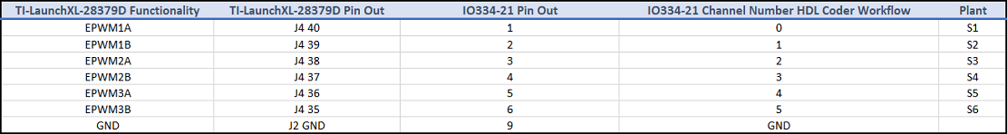
1. Connect the Speedgoat board to the LAUNCHXL-F28379D controller board as shown in this table.

2. For encoder signals, connect the Speedgoat to controller board as shown in this table.


3. For analog signals, connect the Speedgoat to controller as shown in this table.

For more details on the Speedgoat board, see Speedgoat IO-334 and Speedgoat Connection box.
For connections related to the hardware configuration, see LAUNCHXL-F28069M and LAUNCHXL-F28379D Configurations.
Generate Code and Run Model on Target Hardware
1. Complete the hardware connections.
2. Open the target model mcb_pmsm_foc_f28379d.slx. If you want to change the default hardware configuration settings for this model, see Model Configuration Parameters.
3. To ensure that CPU2 is not configured to use the board peripherals intended for CPU1, load a sample program to the CPU2 of the LAUNCHXL-F28379D. For example, you can load the program that operates the CPU2 blue LED by using GPIO31 (c28379D_cpu2_blink.slx). For more information about the sample program or model, see the Task 2 - Create, Configure and Run the Model for TI Delfino F28379D LaunchPad (Dual Core) section in Getting Started with Texas Instruments C2000 Microcontroller Blockset (C2000 Microcontroller Blockset).
4. Check that you have updated the correct motor and inverter parameters in the parameter script mcb_pmsm_foc_f28379d_data.m.
5. Click Build, Deploy & Start on the Hardware tab to deploy the target model mcb_pmsm_foc_f28379d.slx to the controller hardware.
6. If you want to use the default FPGA plant model slrt_ex_pmsm.slx without any modification, obtain the default bitstream file for the hardware configuration supported by the example using the Power Electronics Templates for Simulink Real-Time link. Add the bit-stream file to the MATLAB project and proceed directly to step 7.
If you modify the FPGA plant model or change the hardware configuration, use the HDL Workflow Advisor to regenerate the following files from the modified (or new) FPGA plant model:
Simulink Real-Time application model
slrt_ex_pmsm_gm.slx.
FPGA hardware bitstream file.
Add the two newly generated files to the MATLAB project and then proceed to step 7.
7. Open the Simulink Real-Time application model slrt_ex_pmsm_gm.slx and build the model. Program the FPGA using this model and run it for 500 seconds by executing below lines in MATLAB command window.
tg = slrealtime;
connect(tg);
mdl = 'slrt_ex_pmsm_gm';
open_system(mdl);
modelSTF = getSTFName(tg);
set_param(mdl,"SystemTargetFile",modelSTF);
evalc('slbuild(mdl)');
load(tg,mdl);
tg.setStopTime(500);
start(tg);
8. Click the host model hyperlink in mcb_pmsm_foc_f28379d.slx target model to open the host model.
You can also use the MATLAB project window to open the host model mcb_host_f28379d.slx.
9. Turn the Stop-Start slider switch available in the Simulation Dashboard area to the Start position to allow the model to simulate and run the motor. Run the Open loop control first. Select Ia & Ib ADC counts from Debug signals and observe the ADC counts of the phase current.

10. Take the average value from peak to peak of the sinusoidal ADC count waveform for both Ia and Ib. This is the current offset. Update this current offset in mcb_pmsm_foc_f28379d_data.m for variables inverter.CtSensAOffset and inverter.CtSensBOffset. Build and flash the mcb_pmsm_foc_f28379d.slx model again to the controller hardware. Continue with the host model by running the motor in a closed loop operation.
During simulation, you can turn the switch to the Stop position anytime to immediately stop the motor.
11. In the host model, open the blocks Host Serial Setup, Host Serial Receive, and Host Serial Transmit, and select a Port.
12. Click Run on the Simulation tab to run the host model.
13. Review the logged signals using the Simulation Data Inspector.
