Texas Instruments入门指南 C2000 Microcontroller Blockset
本示例向您展示如何使用 C2000™ Microcontroller Blockset 在 Texas Instruments™ C2000 硬件上运行 Simulink® 模型。
简介
C2000™ Microcontroller Blockset 使您能够生成实时可执行文件并将其下载到您的 TI 开发板。该模块集包含一个 Simulink 模块库,用于配置和访问 Texas Instruments C2000 外设和通信接口。在本示例中,您将学习如何配置一个简单的 Simulink 模型,为任何 TI C2000 硬件生成代码,并在板上运行生成的代码,以定期打开和关闭 LED。本示例向您展示如何配置两个不同的模型在不同的 CPU 核心上运行。
前提条件
如果您是 Simulink 的新用户,我们建议您完成以下步骤:
所需硬件
要运行此示例,您可以使用任何 TI C2000 硬件。为了方便起见,以下硬件模型已预先配置好以运行该示例:
c28069_blink -
TI Piccolo F28069M LaunchPad
c28379D_cpu1_blink -
TI Delfino F28379D LaunchPad
c2838x_cpu1_blink -
TI F2838x(C28x) ControlCard和 180 针控制卡扩展坞
模型

任务 1 - 创建、配置和运行 TI Piccolo F28069M LaunchPad(单核)模型
在这个任务中,您将创建并配置一个简单的模型,该模型使板载 LED 闪烁,并在 TI Piccolo F28069M LaunchPad(单核)上运行。
1.在 MATLAB® 提示符下输入 slLibraryBrowser。这将打开 Simulink 库浏览器。
2.在 Simulink 库浏览器中,导航至库 > C2000™ Microcontroller Blockset 并选择 C2806x 处理器。

3.双击 GPIO 模块。查看模块掩码,其中包含模块的描述以及用于配置相关用户 GPIO 的参数。

4.在 MATLAB 中,选择首页 > 新建 > Simulink 模型。
5.将 GPIO 模块从 C2806x 库拖到模型中。
6.将 Simulink 库中的 Constant 模块拖到模型中。
7.将常量模块的输出连接到每个 GPIO 模块的相应输入之一。请按如下方式配置 GPIO 和常量模块:
a.配置 GPIO 模块,使用引脚 39 控制蓝色 LED,或使用引脚 34 控制红色 LED。
b.请确保已启用“切换 GPIO”选项。启用此选项后,当传递给此模块的输入为 1 时,GPIO 引脚将切换状态。切换频率将基于输入信号的采样时间。

c.对于 Constant 模块,指定采样时间 (0.5)。由于 GPIO 模块中启用了切换选项,这确保 GPIO 在 0.5 秒内为 1,在 0.5 秒内为 0。所以,波形的周期是 1 秒。
8.保存您的模型,然后使用 USB 电缆将 TI Piccolo F28069M LaunchPad 连接到您的计算机。
9.打开已保存的模型,为 F28069M Launchpad 配置模型:
a.打开建模选项选项卡,然后按 Ctrl+E(模型设置)打开配置参数对话框。
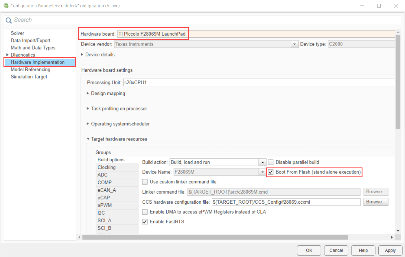
b.前往 Hardware Implementation > Hardware board 并选择 TI Piccolo F2806M LaunchPad。
c.如果应用程序需要加载到闪存中,请确保启用从闪存启动。如果不选择此选项,应用程序将加载到 RAM 中。
d.点击确定。
10.转到硬件选项卡,然后点击构建、部署和启动以生成模型的代码并部署可执行文件。

11.生成的代码会在 F28069M Launchpad 上自动构建和运行。当模型在 F28069M Launchpad 上开始运行时,观察板上的用户 LED 指示灯以 1 秒的周期闪烁。
12.保存您的模型。为了方便起见,我们附赠了 c28069_blink preconfigured 模型。
任务 2 - 创建、配置和运行 TI Delfino F28379D LaunchPad(双核)模型
在这个任务中,您将创建并配置一个简单的模型,该模型使板载 LED 闪烁,并在 F28379D Launchpad(双核)上运行。
F2837xD 是双核处理器。您可以创建 2 个模型。分别生成一个用于 c28379D_cpu1_blink 和 c28379D_cpu2_blink 的可执行文件,以生成 2 个独立的可执行文件。
为 F28379D 的 CPU1 创建模型
1.在 MATLAB 提示符下输入 slLibraryBrowser。这将打开 Simulink 库浏览器。
2.在 Simulink 库浏览器中,导航至库 > C2000™ Microcontroller Blockset 并选择 F2837xD 处理器。

3.双击 GPIO 模块。查看模块掩码,其中包含模块的描述以及用于配置相关用户 GPIO 的参数。

4.针对 TI Delfino F28379D LaunchPad 执行任务 1 中的步骤 4 至 8。为此,请将 GPIO 模块的引脚 34 配置为红色 LED。
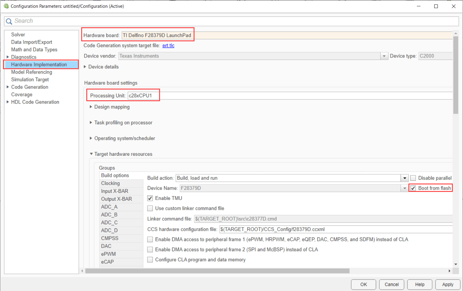
5.选择 TI Delfino F28379D LaunchPad,并确认您的模型所使用的 CPU。对于此任务,请选择 CPU1。此选项会创建并下载 CPU1 的可执行文件。

6.转到硬件选项卡,然后点击构建、部署和启动以生成模型的代码并部署可执行文件。

7.生成的代码会在 F28379D Launchpad 上自动构建和运行。当模型在 F28379D Launchpad 上开始运行时,观察板上的用户 LED 指示灯以 1 秒的周期闪烁。
8.保存您的模型。为了方便起见,我们提供了 c28379D_cpu1_blink preconfigured 模型。
为 F28379D 的 CPU2 创建模型
由于 TI Delfino F28379D LaunchPad 是一款双核处理器,您可以使用 CPU2 选项创建一个类似的模型,并使 LED 闪烁。
1.针对 TI Delfino F28379D LaunchPad,执行任务 2 的步骤 1 至 4。
2.选择 TI Delfino F28379D LaunchPad,并确认您的模型所使用的 CPU。对于此任务,选择 CPU2 并将 GPIO 模块配置为使用引脚 31 控制蓝色 LED。此选项会创建并下载 CPU2 的可执行文件。
3.生成的代码会在 F28379D Launchpad 上自动构建和运行。当模型在 F28379D Launchpad 上开始运行时,观察板上的用户 LED 指示灯以 1 秒的周期闪烁。
4.保存您的模型。为了方便起见,我们提供了 c28379D_cpu2_blink preconfigured 模型。
注意:
请勿使用 CPU1 中使用的 GPIO 引脚。
确保 CPU1 中使用的外围设备不会在 CPU2 中使用。如果 CPU1 和 CPU2 使用相同的外部设备,则该模型可能无法按预期工作。
通过为 TI Delfino F28379D LaunchPad 创建 2 个模型,您可以使 2 个 LED 灯闪烁。一个来自 CPU1,另一个来自 CPU2。
任务 3 - 创建、配置和运行 F2838x(多核)处理器的模型
在这个任务中,您将创建并配置一个简单的模型,使板载 LED 闪烁,并在 F2838x(多核)上运行。
F2838x 是一款多核处理器。您可以创建 3 个模型,分别生成 3 个独立的执行文件:
c2838x_cpu1_blink -
CPU1
c2838x_cpu2_blink -
CPU2
c2838x_armm4_blink -
ARM Cortex-M4
适用于 F2838x(C28x)的 CPU1 和 CPU2
1.在 MATLAB 提示符下输入 slLibraryBrowser。这将打开 Simulink 库浏览器。
2.在 Simulink 库浏览器中,导航至库 > C2000™ Microcontroller Blockset > F2838x > 选择 F2838x_C28x 处理器。

3.双击 GPIO 模块。查看模块掩码,其中包含模块的描述以及用于配置相关用户 GPIO 的参数。

4.通过执行 F2838x(C28x) 处理器的任务 2 中的步骤 4 至 8 来创建 CPU1 和 CPU2 模型。
5.为了方便起见,我们提供了预配置模型(c2838x_cpu1_blink CPU1 和 c2838x_cpu2_blink CPU2)。
注意:请勿使用 CPU1 和 CPU2 中相同的 GPIO 引脚。
对于 F2838x_M4 的 ARM Cortex-M4
1.在 MATLAB 提示符下输入 slLibraryBrowser。这将打开 Simulink® 库浏览器。
2.在 Simulink 库浏览器中,导航至库 > C2000™ Microcontroller Blockset > F2838x > 选择 F2838x_M4 处理器。

3.双击 GPIO 模块。查看模块掩码,其中包含模块的描述以及用于配置相关用户 GPIO 的参数。

4.对 F2838x-M4 处理器执行任务 1 中的步骤 4 至 7,并保存模型。
注意:配置 GPIO 引脚时,请选择适用于 ARM Cortex-M4 处理器的相应引脚。请勿使用与 CPU1 或 CPU2 相同的 GPIO 引脚。
5.打开已保存的模型,为 F2838x-M4 配置模型:
a.打开建模选项选项卡,然后按 Ctrl+E(模型设置)打开配置参数对话框。
b.转到硬件实现 > 硬件板,然后选择 TI F2838x。在处理单元中,选择 *CortexM4。

c.如果应用程序需要加载到闪存中,请确保启用从闪存启动。如果不选择此选项,应用程序将加载到 RAM 中。
d.点击确定。
6.转到硬件选项卡,然后点击构建、部署和启动以生成模型的代码并部署可执行文件。

7.生成的代码基于 F2838x(ARM Cortex-M4)构建,并自动运行。当模型在 F2838x (ARM Cortex-M4) 上开始运行时,观察 GPIO 引脚以 1 秒的周期切换。
8.保存您的模型。为了方便起见,我们提供了 c2838x_armm4_blink preconfigured 模型。
注意:对于像 F2838x 这样的多核处理器,尝试交换 CPU2 和 ARM Cortex-M4 或 CPU1 和 ARM Cortex-M4 之间的 GPIO,并观察 LED 闪烁情况。
其他可以尝试的操作
尝试使用 Texas Instruments C2000 处理器模块库中的其他模块。例如:
使用 Pulse Generator 模块创建并运行一个使 LED 反复闪烁的模型。
使用外部模式示例创建并运行一个使 LED 反复闪烁的模型。