创建模型和生成 C2000 处理器的可执行文件概述
访问 Embedded Coder 模块库
描述如何访问模块库并打开所需的目标硬件。
有了 C2000 Microcontroller Blockset 硬件设置 之后,您就可以打开 C2000™ Microcontroller Blockset 的模块库了。
要打开 C2000 Microcontroller Blockset 库,请在 MATLAB® 命令提示符下输入以下命令:
c2000lib
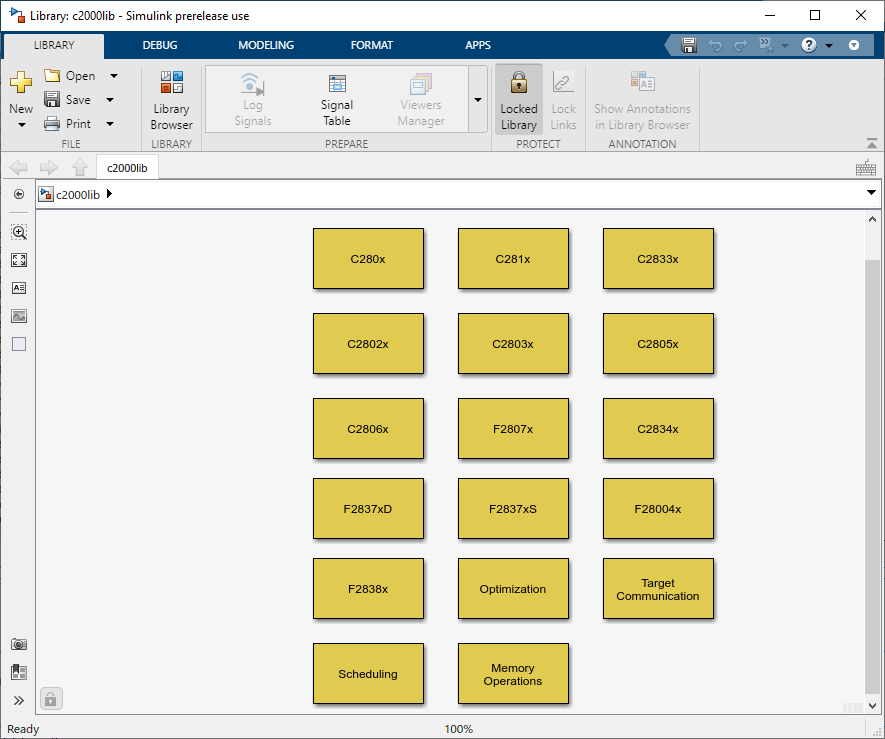
或者,从 Simulink® 库浏览器中找到并选择 C2000 Microcontroller Blockset。
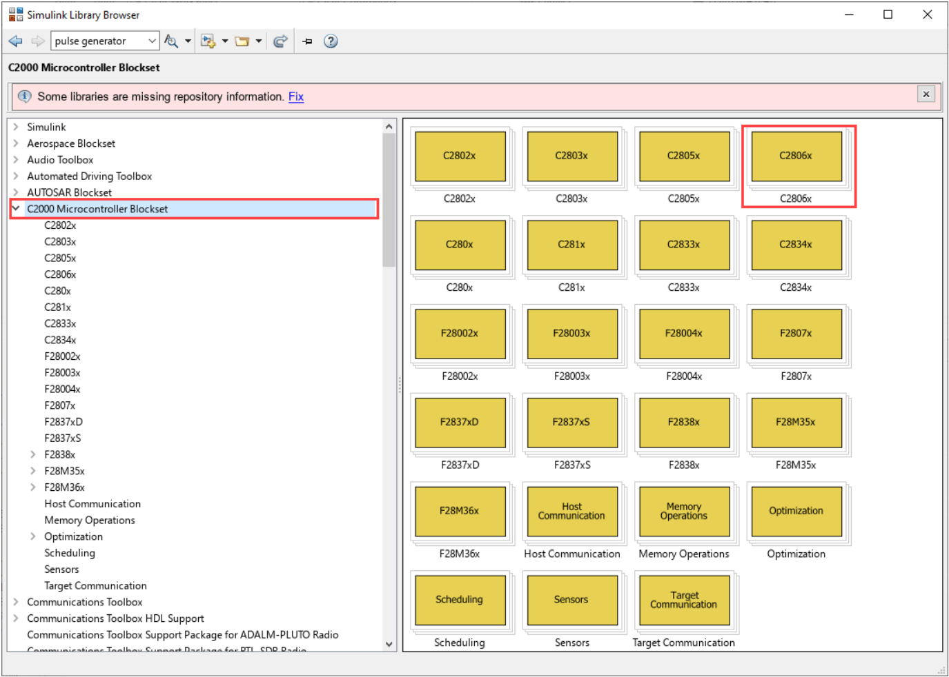
打开所需的目标块以访问设备驱动程序模块。
创建应用程序的实时模型的方式与创建其他 Simulink 模型的方式相同。从以下来源或产品中选择模块来搭建您的模型:
c2000lib模块库中的库(用于处理目标硬件上的输入和输出函数)Simulink Coder™ 软件
Simulink 中的离散时间模块
另一个满足您需求且在离散时间域中运行的模块集
配置目标硬件资源
描述如何使用配置参数配置目标硬件资源。
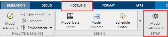
添加模型所需的模块后,打开建模选项卡并点击模型设置。
在配置参数窗口中,点击硬件实现并选择硬件板。
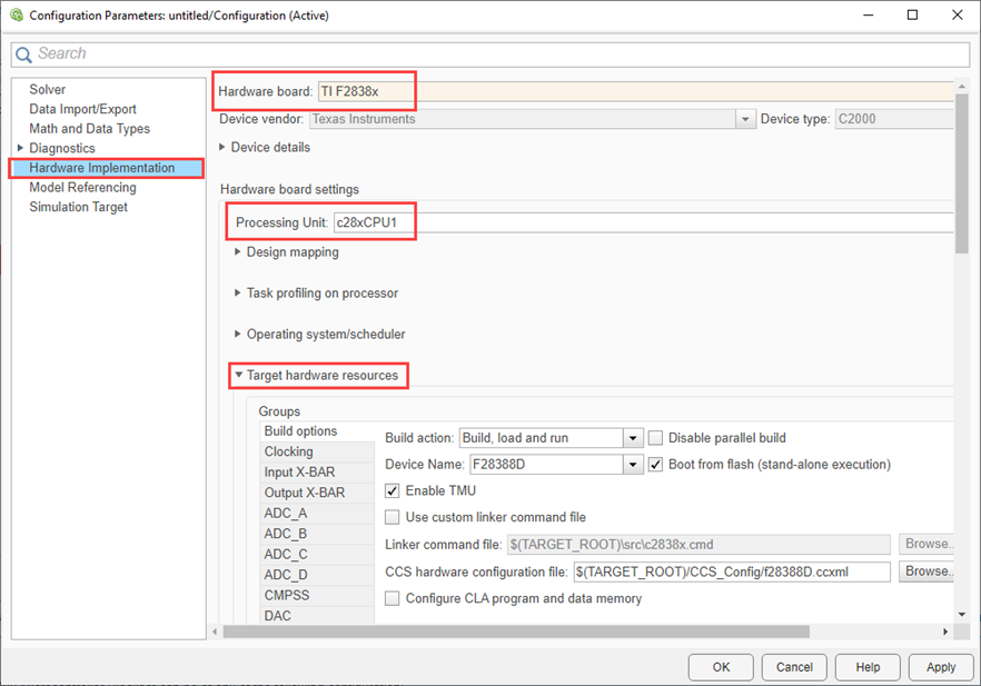
根据需要配置 Target Hardware Resources。有关更多详情,请参考Model Configuration Parameters for Texas Instruments C2000 Processors和Model Configuration Parameters for Texas Instruments F2838x (ARM Cortex-M4)。
注意
C2000 Microcontroller Blockset 支持的外设可以采用以下任何一种配置:
仅限模块- 只能通过模块进行配置的功能。(硬件中断等)
模块+ 配置参数 - 既可以在模块中配置,也可以在配置参数中配置的功能。(ADC、ePWM、SCI、SPI 等)
仅限配置参数 - 只能通过配置参数进行配置的功能。(EMIF、DMA、时钟配置等)
配置硬件选择的其他选项
以下配置设置是作为 TI C2000 硬件选择的一部分自动完成的。如果选择除 TI C2000 目标之外的其他硬件,则以下配置将重新配置为默认值。
当将 ModelReferenceNumInstancesAllowed 从 Multiple 更改为 One 时,使用 XCP over CAN 运行外部模式时,子模型中记录的信号(输出信号)的名称将会改变。
如果设置为
One,您会获得<ChildModelName>_B.<outputsignalname>如果设置为
Multiple,您会获得<TopModelName>_DW.Model_InstanceData.rtb.<outputsignalname>
hCS 是该模型的配置集对象。您可以使用以下命令获取配置集对象。
hCS = getActiveConfigSet(mdlname);
转到 配置参数 > 数学和数据类型 并将非规范数的仿真行为参数设置为
Flush to Zero (FTZ)。set_param(hCS,'DenormalBehavior', 'FlushToZero');
转到 配置参数 > 数学和数据类型 并将数据类型未定时默认使用的类型参数设置为
Single。set_param(hCS,'DefaultUnderspecifiedDataType','single');
前往 配置参数 > 代码生成 > 接口,并将代码替换库参数设置为
TI C28x,以用于 TI C2000 处理器的 C28x 内核。set_param(hCS,'CodeReplacementLibrary','TI C28x');
前往 配置参数 > 代码生成 > 优化 > 高级参数,根据处理器选择最大堆栈大小(字节) 参数。
序号 设备系列 最大堆栈大小(字节) 1 F281x
5122 F2802x、F2803x、F2805x、F2834x、F2804x、F28M35x、F28M36x
7683 F2806x、F2837x、F28004x、F28003x、F2838x、F28002x
10244 ARM 核 2560set_param(hCS,'MaxStackSize','1024');
转到 配置参数 > 硬件实现 > 设备详细信息 并将支持 long long 参数设置为
On。set_param(hCS,'ProdLongLongMode','on');
注意
使用 CLA 的模型需要将 long long 模式设置为
off。转到 配置参数 > 代码生成 > 优化 并将删除根级 I/O 零初始化参数设置为
On。set_param(hCS,'ZeroExternalMemoryAtStartup', 'on');
当模型需要在定制板的 SIL 模式下运行时,请确保完成上述配置。在 SIL 模式下,请确保完成以下附加设置:
转到 配置参数 > 代码生成 > 验证 并将启用可移植字长参数设置为 On。这将确保在 PIL 和 SIL 模式下,同一模型生成的代码完全相同。
配置代码生成的其他选项
您可以按照以下步骤配置代码生成窗格中代码生成所需的其他选项,例如编译器标志、CRL 和自定义代码等。
在配置参数窗口中,点击代码生成窗格。
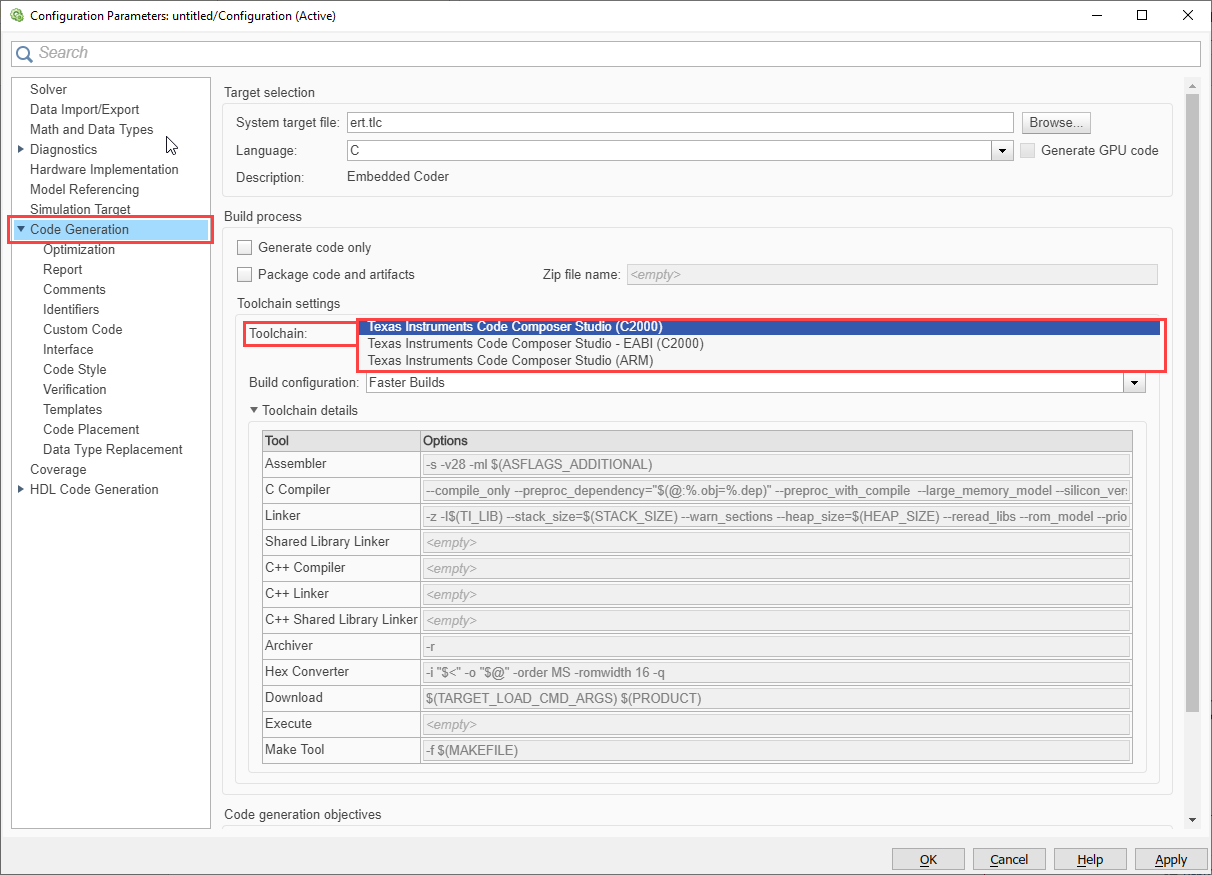
COFF ABI 格式会将 Simulink 中的 double 数据类型解释为 C28x 处理器的 32 位浮点数,而 ELF ABI 格式会将 Simulink 中的 double 数据类型解释为 TI F2838x (C28x™)、TI F2807x、F2837x、F28004x、F28003x、F28002x、F28001x、F28P5x 处理器的 64 位浮点数。有关 COFF ABI 和 ELF ABI 的更多信息。有关更多信息,请参阅Exploring TI C2000 Toolchain Options
编译过程下的仅生成代码选项允许您指定生成代码还是生成可执行文件。有关更多信息,请参阅 仅生成代码 (Simulink Coder)。
您可以选择编译配置选项来获取代码编译所需的编译器标志。
更快编译
更快运行
调试
指定
使用指定选项编辑工具选项列,以添加任何其他标志。有关更多信息,请参阅 编译配置 (Simulink Coder)、Enhance Code Execution Speed in TI C2000 Simulink Applications 和 Exploring TI C2000 Toolchain Options。
代码生成 > 优化类别包含用于提高模型仿真速度和提高生成代码性能的参数。有关更多信息,请参考模型配置参数:代码生成优化 (Simulink Coder)。
代码生成 > 报告类别包含用于生成和自定义代码生成报告的参数。有关更多信息,请参考模型配置参数:代码生成报告 (Simulink Coder)。
代码生成 > 自定义代码类别包含用于将自定义 C 代码插入到生成的代码中的参数。有关更多信息,请参考模型配置参数:代码生成自定义代码 (Simulink Coder)。
代码生成 > 接口类别包含用于配置生成的代码和代码替换库 (CRL) 接口的参数。有关更多信息,请参考模型配置参数:代码生成接口 (Simulink Coder)。
代码生成 > 验证类别包括 SIL 和 PIL 仿真的代码验证和性能分析参数,以及配置探查选项。此外,您还可以配置以下选项并执行独立于 SIL 和 PIL 仿真的探查:
测量任务执行时间 - 通过在配置参数中启用此参数,您可以执行实时性能探查。
测量函数执行时间 - 在配置参数中配置以获得不同级别的探查(任务、子系统或函数)。相应地添加了探查逻辑。由于测量时间上的探查逻辑,将会产生额外的开销。目前异步探查仅支持硬件中断。
关闭 - 用相应的任务测量时间
课程 - 仅任务、参考模型和子系统
详细说明 - 任务、参考模型、子系统、模块/函数内部化和步骤逻辑
保存选项 - 选择仅保存为摘要数据或保存所有数据以获取详细的时间线(在配置参数中)。C2000 不支持指标选项。
通过编译、加载和运行进行探查
探查数据 - 在 MATLAB 命令行窗口中运行以下代码以获取探查数据、报告和任务调度。
探查数据 - 从目标硬件收集探查数据并将其存储在变量中。
codertarget.profile.getData('ModelName')探查报告 - 提供基于探查数据的 HTML 报告。
executionProfile.report
任务调度 - 将不同任务和函数的调度可视化。
executionProfile.schedule
有关更多信息,请参阅 模型配置参数:代码生成验证 (Embedded Coder) 和 Real-Time Code Execution Profiling。
通过监控和调节进行探查
您可以使用 C2000 Microcontroller Blockset 来分析在 Texas Instruments® C2000 板上以可执行文件形式运行的生成代码的实时执行情况,该板具有串行 XCP 和 TCP/IP 接口 XCP。有关更多信息,请参阅 Code Execution Profiling on Texas Instruments C2000 和 Troubleshooting External Mode Issues。
使用 PIL 进行探查
您可以配置探查选项并将其与 PIL 模式一起使用。
生成代码、构建并下载可执行文件
配置好模型的硬件资源和代码生成后,您可以生成代码,构建实时可执行文件并将其下载到您的 Texas Instruments 开发板。Simulink Coder 软件会自动生成 C 代码,并根据硬件模块指定的配置参数,在您的 Simulink 模型中插入 I/O 设备驱动程序。
注意
避免在 makefile 中使用关键字或预定义标识符(例如 CPU1 或 CPU2)来命名模型。
当模型路径包含非 ASCII 字符时,会发生
Microsoft Visual C++ Runtime Library错误。为避免此问题,请确保代码生成目录路径仅使用 ASCII 字符。
使用 S-function 创建自定义设备驱动模块时,请使用 MATLAB_MEX_FILE 宏来区分仿真和代码生成行为。例如,在生成用于创建 MEX 文件的代码中包含 Texas Instruments 头文件时,请使用 #else 部分来避免编译错误,如下所示:
#ifdef MATLAB_MEX_FILE /*
/* Simulation behavior */
#else
/* Code generation behavior*/
#endif
在构建操作期间,Texas Instruments 交叉编译器会根据生成的代码构建可执行文件。构建操作将为每个源文件 (.c) 生成依赖文件 (.dep),它将使用这些依赖文件来创建目标文件 (.obj)。然后使用链接器命令文件链接目标文件,以创建映射文件 (.map) 和可执行文件 (.exe) 文件。
可以使用选项 Hardware Implementation > Target Hardware Resources > Build options > Use custom linker 修改默认链接器命令文件,或者根据需要提供不同的链接器命令文件。
注意
当数据类型为 CAN_MESSAGE 时,输出端口采样时间不能是恒定的。在输入端口使用 Zero Order Hold 模块来强制执行非恒定的采样时间,或者修改 S-Function 以使用 SS_OPTION_DISALLOW_CONSTANT_SAMPLE_TIME。有关更多信息,请参阅https://in.mathworks.com/matlabcentral/answers/405090-sample-time-error-when-can-pack-block-has-constant-block-input。
依赖项构建
后续构建仅在源文件或头文件发生更改或 make 文件更新时才会使用依赖文件重新编译目标文件。依赖项构建使用 Windows® PowerShell 来更新依赖项文件。因此,如果计算机中不存在 Windows PowerShell,则不会使用依赖项构建,并且会重新编译目标文件。
并行编译
该构建过程将利用主机计算机的多个核心,通过启用并行构建来更快地编译目标文件。如果构建失败,这可能会导致构建日志中显示的消息顺序出现问题。您可以使用 Hardware Implementation > Target Hardware Resources > Build options > Disable parallel build 禁用此选项。
如果在 Hardware Implementation > Target Hardware Resources > Build options > Build action 参数中选择 Build, load and run 选项,则生成的执行文件将自动下载到目标位置。
如果应用程序需要加载到闪存中,请选择选项 Boot from Flash。如果不选择此选项,应用程序将加载到 RAM 中。Hardware Implementation > Target Hardware Resources > Build options > Boot from Flash。
默认情况下,将提供目标配置文件,以支持下载到所选硬件板的控制卡或启动板。若您拥有任何自定义电路板,可在 Hardware Implementation > Target Hardware Resources > Build options > Select target configuration 选项中提供您自己的目标配置文件。
对于 CCS v5 及更高版本,在构建过程中还会生成 CCS 工程文件。您可以使用此工程文件在 CCS IDE 中进行调试。
注意
C2000 Microcontroller Blockset 不支持快速加速器仿真。
另请参阅
从模型创建 CCS 工程 | Enhance Code Execution Speed in TI C2000 Simulink Applications | 使用 Custom Code 模块测量 TI C2000 上的代码执行时间 | Troubleshooting External Mode Issues