Estimate PMSM Parameters Using FPGA-Based Motor Control Development Kit
This example shows how to estimate parameters of a permanent magnet synchronous motor (PMSM) using blocks from Motor Control Blockset™ on an FPGA device (Trenz Electronic™ Motor Control Development Kit TE0820).
Motor parameter estimation is vital for implementing motor control algorithms accurately. Accurate motor parameters enable the algorithm to compute the control parameters with precision. Therefore, an accurate representation of motor parameters results in efficient speed tracking when you run PMSMs using control techniques such as field-oriented control (FOC). Motor parameter estimation also enables you to verify the parameter values provided by the motor datasheet.
The example shows you how to generate HDL code for the parameter estimation algorithm. The example includes a MATLAB® project with the models and the reference design. Use the project with HDL Workflow Advisor for bit stream generation and for running an external mode model to interact with the processor.
You can apply the techniques shown in this example to partition and deploy the parameter estimation algorithm. This image shows the generalized workflow from model simulation to deployment of the algorithm to embedded hardware board.
The example supports using a quadrature encoder sensor to detect the motor position during simulation and hardware deployment.
First, simulate a system test bench to understand the design of the parameter estimation algorithm. Then explore the design to see how the algorithm is partitioned. The high rate portion of the algorithm is partitioned into a model that is configured for HDL code generation. The low rate portion of the algorithm is partitioned into a model that is configured for C code generation. Generate C and HDL code from these models and learn how you can integrate this code into your design.
After exploring C and HDL code (model) for the algorithm, use automated deployment of code into the reference frameworks for the processor and programmable logic. Then, execute a test on the deployed application, log the results, and compare them with the simulation results.
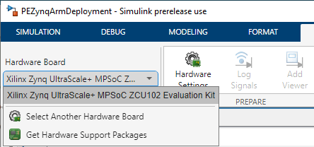
Because this example deploys a bitstream and ARM® executable to a Xilinx® Zynq® hardware, you must set up the Xilinx Zynq hardware board before starting the example. To ensure that you have set up the environment correctly, follow and complete the Get Started with IP Core Generation from Simulink Model (HDL Coder) example using your hardware configuration before starting this example. The figure shows the Hardware Board selection used in this demo.
Required Products
To run this example, you need:
MATLAB®
Simulink®
Embedded Coder®
Embedded Coder Support Package for Xilinx Zynq Platform
HDL Coder™
HDL Coder Support Package for AMD FPGA and SoC Devices
Motor Control Blockset
Required Hardware
Trenz Electronic Motor Control Development Kit TE0820 (Xilinx Zynq UltraScale+ and ZU2CG-1E MPSoC Module) with these components:
◦ TEB0707-02 carrier board
◦ CR00140-02 driver module
Create Working Copy of MATLAB Project
To begin, create a working copy of the MATLAB project.
Use the following command to open the MATLAB project:
mcb_foc_fpga_demo_start
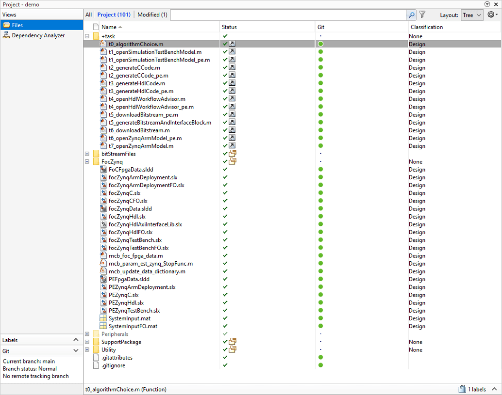
The +task folder in the project contains the scripts to automate different activities. The following image provides a summary of activities and dependencies in the MATLAB project. For more information about MATLAB projects, see What Are MATLAB Projects in Simulink?
Note: The PEZynqC model automatically computes the ADC (or current) offset values after deployment. To disable this functionality (enabled by default), change the value of the variable paramAdcEnablecalibration to 0 in the PEZynqC/ADC_Calibration subsystem or in the PEFpgaData.sldd data dictionary. If you disable this functionality, you can compute the ADC offset manually and update it in the paramAdcCountAtZeroAmpere variable in the PEZynqC/ADC_Calibration subsystem.
Measure the signals highlighted in the following image. The measured values represent the ADC offsets. Update these values in the variable paramAdcCountAtZeroAmpere.
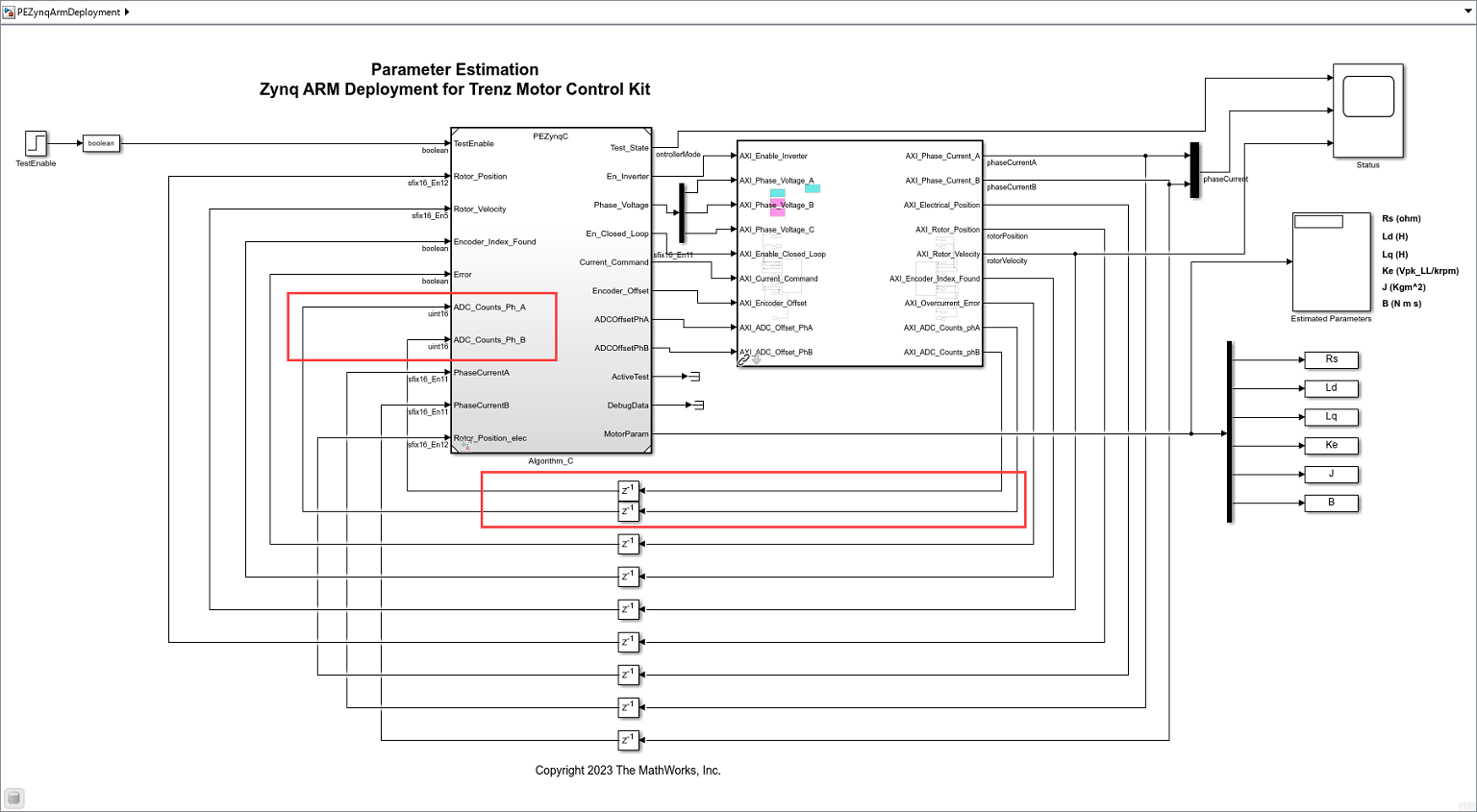
◦ Make sure that you power OFF the inverter before calibrating the ADC offsets for phase A and phase B.
Simulate Algorithm Behavior
You can use the project shortcuts to open the Simulink models and simulate the algorithm behavior.
1. Click Project Shortcuts to view the available project shortcuts.
2. You can right-click the shortcuts to edit, open, and configure them.
3. To open PEZynqTestBench, click the t1_openSimulationTestBenchModel_pe project shortcut button or use the following MATLAB command.
task.t1_openSimulationTestBenchModel_pe
The Motor_And_Load subsystem consists of a mathematical model of surface PMSMs (from Motor Control Blockset), motor load, an encoder, and a current sensor. The Controller_Algorithm subsystem includes an algorithm for I/O engineering unit conversion, an electrical position calculation algorithm, a rotor velocity calculation algorithm, a test selection mechanism, and the parameter estimation algorithm. The C/D and D/C subsystems convert the data from continuous-time, variable time step solver and floating-point data type, to discrete-time, fixed time step solver and fixed-point data type, and vice-versa during simulation.

4. On the Simulation tab of the Simulink Toolstrip, click Run to simulate the model.
5. When the model finishes running, the Estimated Parameters display block in the PEZynqTestBench model displays the estimated motor parameters. Compare these parameter values with the values in the motor datasheet or other sources.
The following plot shows the simulation system response as captured by the Simulation Data Inspector.

Example Design Architecture
The following figure shows the architecture of the parameter estimation algorithm design, which is partitioned between a module that runs in embedded software and another module that runs on the FPGA hardware.
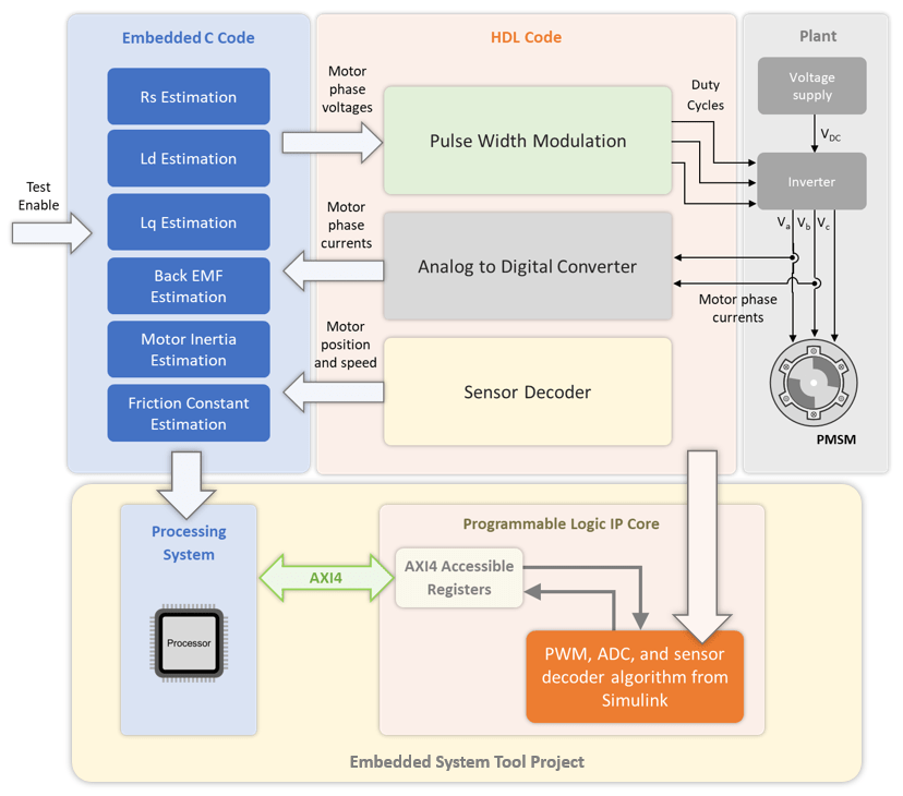
The parameter estimation algorithm design runs in embedded software using a processor. The current or torque control design supports HDL code generation and runs on the FPGA hardware.
The hardware part of the design is enclosed in the models PEZynqHdl.slx. This part uses HDL Workflow Advisor to define and generate an HDL IP core, which includes components such as AXI4 accessible registers, AXI4 interfaces, external ports, and ADC.
Using the HDL Workflow Advisor IP core generation workflow, you insert this IP core into a reference design and generate an FPGA bitstream that runs on the SoC hardware. You can also use HDL Workflow Advisor to generate a software interface containing AXI driver blocks that connects the embedded software and the FPGA hardware. This example uses external mode to interface with the target model.
For more details, see Hardware-Software Co-Design Workflow for SoC Platforms (HDL Coder) and HDL IP Core Generation (HDL Coder).
Partition Algorithm and Generate Code
You can partition the controller algorithm into sections that separately generate C code (for the designed software) and HDL code (for the designed hardware). See the reports created during the code generation step to determine ways to integrate the generated code and build an application according to your own embedded design.
1. In the PEZynqTestBench model, open the Controller_Algorithm subsystem. The controller algorithm contains the Algorithm_C and Algorithm_HDL blocks that reference the following models respectively:
PEZynqC
PEZynqHdl
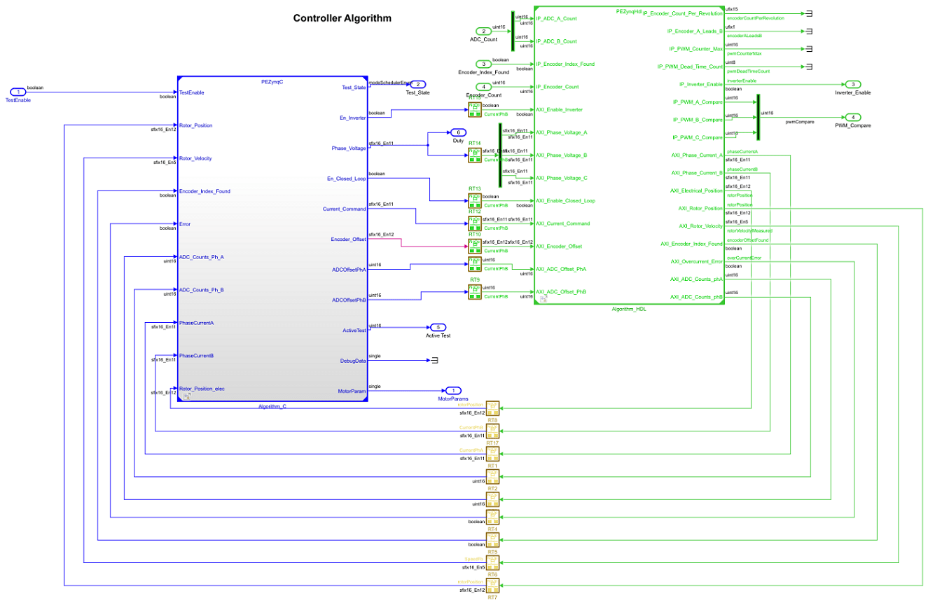
The PEZynqC model contains the portion of the algorithm to be implemented in software (ARM processor). Similarly, the PEZynqHdl model contains the portion of the algorithm to be implemented on the FPGA hardware.
The data dictionary stores the parameters for the model. To access and modify the parameters, select:
Modeling > Model Explorer > focZynqTestBench > ExternalData
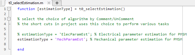
Click the t0_selectEstimation project shortcut or use the following MATLAB command to open the t0_selectEstimation.m file:
task.t0_selectEstimation
Select type of motor parameters the example should estimate
Uncomment the type of motor parameters (electrical or mechanical) that you want the example to estimate. Comment the type of parameters that you do not want the example to estimate. For example, the following figure shows that the example is set to estimate mechanical parameters only.
To generate and deploy the HDL code for the electrical or mechanical parameter estimation algorithm, follow the next steps in this section. Then follow the procedure described in the sections Set Up Xilinx Zynq Platform and Motor Boards and Deploy Bitstream to Programmable Logic.
To generate and deploy the C code for the electrical or mechanical parameter estimation algorithm, follow steps 2 and 3. Then follow the procedure described in the sections Set Up Xilinx Zynq Platform and Motor Boards and Deploy Executable to ARM Processor.
2. To open the model PEZynqC, generate C code, and generate a report, click the t2_generateCCode_pe project shortcut or use the following MATLAB command.
task.t2_generateCCode_pe
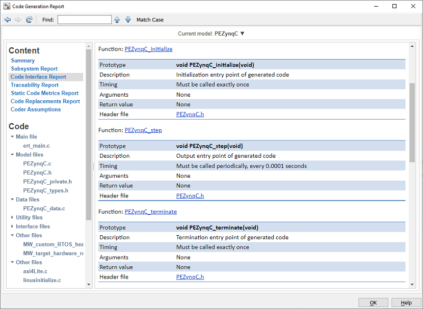
The PEZynqC model contains the test selection mechanism and the parameter estimation algorithm.

3. The Code Generation Report shows how the generated code corresponds to the model. If you are new to the Code Generation report, you can start with the Code Interface Report to view the function interface of the code. The C code is portable and you can integrate it with any floating-point embedded processor that uses an ANSI-C compiler. For more information on the Code Generation Report, see Reports for Code Generation (Simulink Coder).
4. To open the model PEZynqHdl, generate HDL code, and generate a report, click the t3_generateHdlCode project shortcut or use the following MATLAB command.
task.t3_generateHdlCode_pe
The PEZynqHdl model contains the algorithm for calculating electrical position and rotor velocity and for performing over-current checks.
Note: When estimating electrical parameters, the PEZynqHdl model uses a sampling time of 1 microsecond, whereas, for the mechanical parameters, the model uses a sampling time of 10 microseconds.

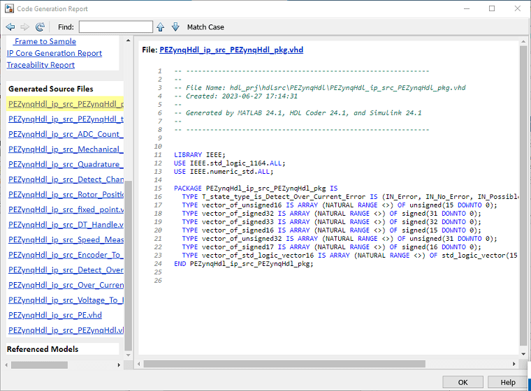
5. The Code Generation Report shows how the HDL code corresponds to the model. If you are new to the Code Generation report, you can start by exploring the Generated Source Files pane of the report and selecting the PEZynqHdl_ip_src_PEZynqHdl_pkg.vhd file that contains the entity specification. The HDL code for the algorithm is portable and you can integrate it with any FPGA hardware that supports VHDL code.
Set Up Xilinx Zynq Platform and Motor Boards
Use this procedure to connect and set up the hardware required for this example.
1. Set up the Xilinx Zynq hardware platform. For information about the hardware setup, see Install Support for AMD SoC Boards (Embedded Coder). Install both Embedded Coder Support Package for Xilinx Zynq Platform and HDL Coder Support Package for AMD FPGA and SoC Devices.
2. Connect the Trenz Electronic Motor Control Development Kit TE0820 as shown in this image:
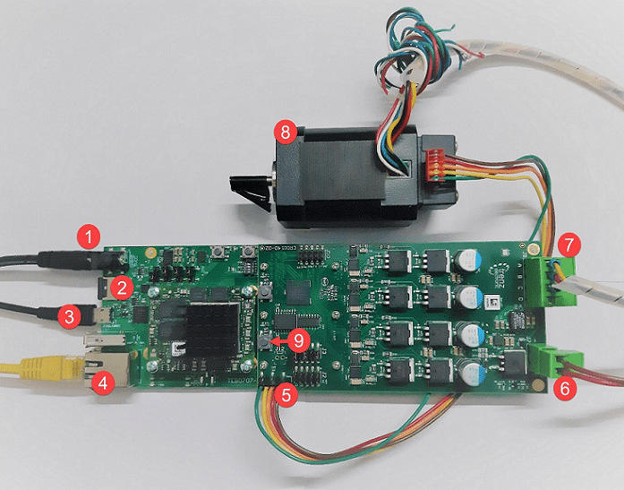
The components listed in this image are as follows.
1. 5 V DC Power Supply
2. SD - Card
3. Micro USB cable for UART and JTAG
4. Ethernet cable
5. Encoder connector
6. 24 V DC Power Supply
7. Motor Power cable (A, B, C)
8. 24 V Brushless DC Motor
9. Switch 1 (S1) controls power to the driver board
3. Ensure that jumper J4 on the carrier module is set to SD and J3 on the motor driver card is set up for a single ended encoder.

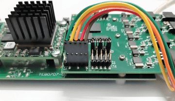
4. Insert the encoder cable as shown in the picture below.
Note: Step 4 is required only if you are using a control algorithm based on quadrature encoder sensor.
5. Download the Trenz TE0820 Linux Image, extract the ZIP archive, and copy the contents to the microSD card. Insert the microSD card in the J8 connector.
6. After you program the FPGA bitstream, press the S1 switch located on the motor driver card once to connect the 24V power supply to the MOSFETS. In case the device behaves unexpectedly, use the S1 switch to disconnect the power.
Deploy Bitstream to Programmable Logic
Use HDL Workflow Advisor to generate the HDL code for the algorithm. Complete the following steps to package HDL into an IP core, integrate the IP core into a Xilinx reference design, and then create a bitstream.
1. Click the t4_openHdlWorkflowAdvisor_pe project shortcut or use the following MATLAB command to open HDL Workflow Advisor.
task.t4_openHdlWorkflowAdvisor_pe
2. In the HDL Workflow Advisor > 1. Set Target > 1.1 Set Target Device and Synthesis Tool group, set the Target platform to Trenz TE0820 with CR00140. Trenz TE0820 with CR00140 is a Vivado® reference design containing the ADC, encoder, and PWM components. For more information about creating this reference design, see Define Custom Board and Reference Design for AMD Workflow (HDL Coder).

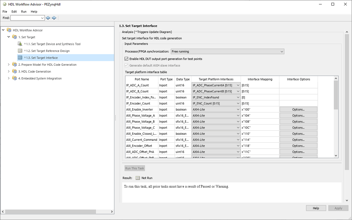
3. Select 1.3. Set Target Interface to identify the ports. The Target Platform Interfaces column entries that have the prefix "IP" indicate the connections that are registered with the Trenz motor control reference design.
4. Select 4.3 Build FPGA Bitstream > Run to Selected Task to generate the HDL code for the algorithm and create the FPGA bitstream from the Xilinx reference design.

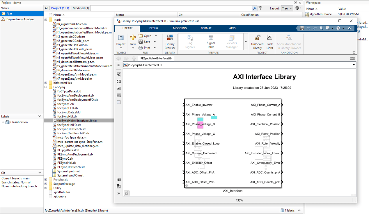
5. Follow the progress of the bitstream generation on the new DOS command prompt that opens. In addition to generating the bitstream, the customized target generates the focZynqHdlAxiInterfaceLib software interface library. The library contains an AXI_Interface block. The AXI_Interface block, which contains the AXI4-Lite interface components, provides connectivity from the model deployed on the ARM processor to the model deployed on the programmable logic.
6. Run task 4.4 Program Target Device or click the t5_downloadBitstream_pe project shortcut to program the FPGA. Alternatively, you can use the following MATLAB command to perform this action:
task.t5_downloadBitstream_pe
Deploy Executable to ARM Processor
You can generate the C code for the controller and automatically integrate this code with a Linux® reference framework to build, deploy, and run the model as an executable on the ARM processor. You can then compare the data logged by the model running on the processor with the simulation results.
1. Click the t6_openZynqArmModel project shortcut button to open the PEZynqArmDeployment model. Alternatively, you can use the following MATLAB command to open the model:
task.t6_openZynqArmModel_pe
The PEZynqArmDeployment model can generate C code, automatically integrate this code with a Linux ARM reference framework, and deploy the executable to the ARM processor on the Xilinx Zynq platform. The deployable model uses references to the original controller model and contains test stimulus, scope, and AXI_Interface library block that you created in the section Deploy Bitstream to Programmable Logic.
Note: When estimating electrical parameters, the Algorithm_C subsystem refers to the PEZynqCElecEst Simulink model. When estimating the mechanical parameters, the Algorithm_C subsystem refers to the PEZynqCMechEst Simulink model. For example, in the following figure, Algorithm_C refers to PEZynqCMechEst when the example is configured for mechanical parameter estimation.
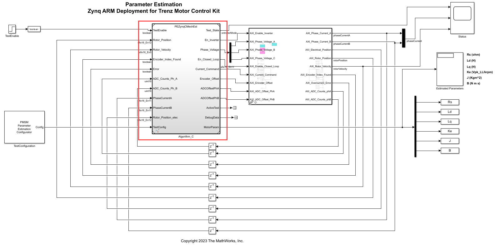
On the Hardware tab, click Monitor & Tune to build, deploy, and run the model as an executable on the ARM processor. The system compiles the generated code against the reference framework to create an executable. Simulink monitors the signals and shows them in the scope when the model is executing.
Press the S1 switch located on the Motor Driver card once. This connects the 24V power supply to the MOSFETS, after which the motor should run for 8 seconds. If you see any unexpected behavior in the device, use the S1 switch to disconnect the power.
3. Observe the estimated parameters in the Estimated Parameters display block and compare them with the parameters previously computed by the PEZynqTestBench model.
See Also
HDL IP Core Generation (HDL Coder)
See Also
Apps
Blocks
- PMSM Rs Estimator | Ld Estimator | Lq Estimator | PMSM Mechanical Parameter Estimator | PMSM Parameter Estimation Configurator | ACIM Parameter Estimation Configurator | Id0 Estimator | ACIM Rs Estimator | RrL Estimator | ACIM Mechanical Parameter Estimator
Topics
- Estimate PMSM Parameters Using Custom Hardware
- Estimate Induction Motor Parameters Using Parameter Estimation Blocks
- Estimate PMSM Parameters Using Parameter Estimation Blocks
- Estimate PMSM Parameters Using Parameter Estimation Blocks on Real-Time Systems
- Run-Time Parameter Estimation of PMSM Using Sensor Feedback
- Generate Motor Control Models for Selected Algorithm and Hardware