Hardware-Software Co-Design Workflow for SoC Platforms
The HDL Coder™ hardware-software co-design workflow helps automate the deployment of your MATLAB® and Simulink® design to a Zynq®-7000 platform or Intel® SoC platform. You can explore the best ways to partition and deploy your design by iterating through the following workflow.
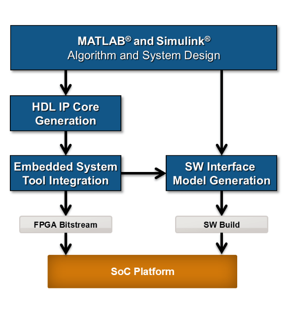
MATLAB and Simulink Algorithm and System Design: You begin by implementing your design in MATLAB or Simulink. When the design behavior meets your requirements, decide how to partition your design: which parts you want to run in hardware, and which parts you want to run in embedded software.
The part of the design that you want to run in hardware must use MATLAB syntax or Simulink blocks that are supported and configured for HDL code generation. See:
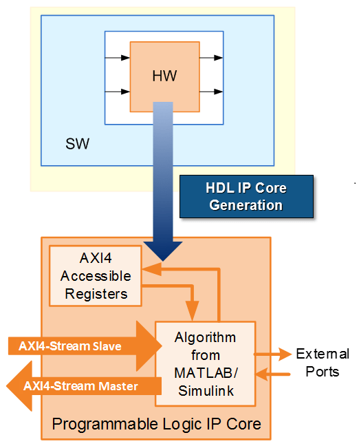
HDL IP Core Generation: Enclose the hardware part of your design in an atomic Subsystem block or MATLAB function, and use the HDL Workflow Advisor to define and generate an HDL IP core.
The following diagram shows a design that has been partitioned into a hardware part, in orange, and software part, in blue. HDL IP core generation creates an IP core from the hardware part of the model. The IP core includes hardware interface components such as AXI4 accessible registers, AXI4 or AXI4-Lite interfaces, AXI4-Stream or AXI4-Stream Video interfaces, AXI4 Master interfaces, and external ports.
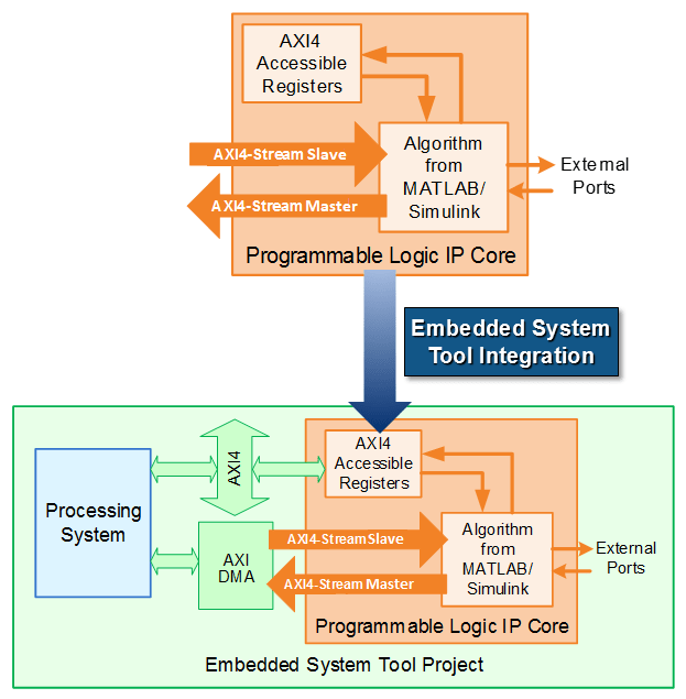
Embedded System Tool Integration: As part of the HDL Workflow Advisor IP core generation workflow, you insert your generated IP core into a reference design, and generate an FPGA bitstream for the SoC hardware.
The reference design is a predefined embedded system integration project. It contains all elements the Intel or Xilinx® software needs to deploy your design to the SoC platform, except for the custom IP core and embedded software that you generate.
The following diagram illustrates the relationship between the reference design, in green, and the generated IP core, in orange.
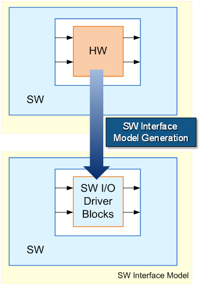
SW Interface Generation (requires a Simulink license and Embedded Coder® license): In the HDL Workflow Advisor, after you generate the IP core and insert it into the reference design, you can optionally generate a software interface model, host interface model, and host interface script. The software interface model is your original model with AXI driver blocks replacing the hardware part. The host interface model enables you to write to or read from the memory-mapped locations on the target hardware over a JTAG or Ethernet cable by using the AXI Manager Write and AXI Manager Read blocks. The host interface script is a MATLAB file that is generated based on the reference design and Target platform interface table settings. It contains commands that enable you to connect to the target hardware, and to write to or read from the generated IP core by using the AXI driver blocks or the AXI Manager.
If you have an Embedded Coder license, you can automatically generate the software interface model and host interface script, generate embedded code from it, and build and run the executable on the Linux® kernel on the ARM® processor. The generated embedded software includes AXI driver code generated from the AXI driver blocks that controls the HDL IP core.
If you do not have an Embedded Coder license or Simulink license, you can write the embedded software and manually build it for the ARM processor. See Generate and Manage FPGA I/O Host Interface Scripts
The following diagram shows the difference between the original model and the software interface model.
SoC Platform and External Mode PIL: Using the HDL Workflow Advisor, you program your FPGA bitstream to the SoC platform. You can then run the software interface model in external mode, or processor-in-the-loop (PIL) mode, to test your deployed design.
If your deployed design does not meet your design requirements, you can repeat the workflow with a modified model, or a different hardware-software partition.
See Also
Targeting FPGA & SoC Hardware Overview