使用 Simscape Electrical 对逆变器中的开关动态特性进行建模
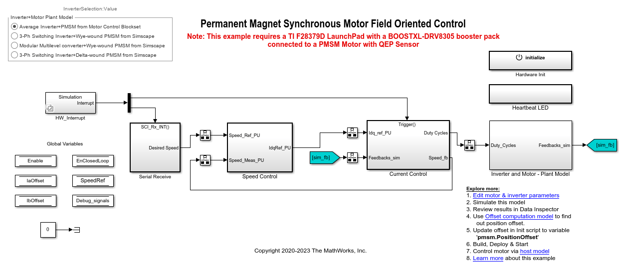
此示例使用磁场定向控制 (FOC) 来控制三相永磁同步电机 (PMSM) 的转速。它为您提供使用以下 Simscape™ Electrical™ 模块来代替 Motor Control Blockset™ 中 Average Value Inverter 模块的选项:
转换器(三相)
理想半导体开关
该示例还为您提供使用 Simscape Electrical 中的 PMSM 模块代替 Motor Control Blockset 中的 Surface Mount PMSM 模块的选项。这些 Simscape Electrical 模块使您能够生成高保真度仿真。
磁场定向控制 (FOC) 需要转子位置的实时反馈。此示例使用正交编码器来测量转子位置。有关 FOC 的详细信息,请参阅磁场定向控制。
您可以使用此示例通过使用不同逆变器对目标模型进行仿真,并监控每个逆变器的反馈电流。您也可以生成代码并将主机模型与目标模型结合使用。
模型
该示例包含模型 mcb_ee_pmsm_foc。
此模型既可用于仿真,也可用于代码生成。
必需的 MathWorks 产品
要对模型进行仿真,您需要:
Motor Control Blockset
Simscape Electrical
要生成代码并部署模型,您需要:
Motor Control Blockset
Embedded Coder®
C2000™ Microcontroller Blockset
Fixed-Point Designer™(仅在优化代码生成时需要)
前提条件
1.获取电机参数。我们对 Simulink® 模型提供了默认电机参数,您可以用电机数据表或其他来源的值替换这些默认值。
不过,如果您有电机控制硬件,则可以通过使用 Motor Control Blockset 参数估计工具来估计要使用的电机的参数。有关说明,请参阅使用 Motor Control Blockset 参数估计工具估计电机参数。
参数估计工具使用估计的电机参数更新 motorParam 变量(在 MATLAB® 工作区中)。
2.如果您从数据表或其他来源获得电机参数,请在与 Simulink 模型相关联的模型初始化脚本中更新电机参数和逆变器参数。有关说明,请参阅估计控制增益并调节控制参数。
如果您使用参数估计工具,则可以在模型初始化脚本中更新逆变器参数,但不能更新电机参数。该脚本会自动从更新后的 motorParam 工作区变量中提取电机参数。
仿真模型
此示例支持仿真。请按照以下步骤仿真模型。
1.打开目标模型 mcb_ee_pmsm_foc。
2.在目标模型的 InverterSelection 单选按钮组中选择以下选项之一来对逆变器变体进行仿真:
Average Inverter+PMSM from Motor Control Blockset - 选择此选项以使用 Average Inverter 和 Surface Mount PMSM 模块。
3-Ph Switching Inverter+Wye-wound PMSM from Simscape - 选择此选项以使用 Converter (Three-Phase) 和 PMSM 模块。
Modular Multilevel converter+Wye-wound PMSM from Simscape - 选择此选项以使用 Ideal Semiconductor Switch 和 PMSM 模块。此选项使用低电压对 Simscape Electrical 模块化多电平转换器进行仿真。
3-Ph Switching Inverter+Delta-wound PMSM from Simscape - 选择此选项以使用 Converter (Three-Phase) 和 FEM-Parameterized PMSM 模块。
3.从 InverterSelected 单选按钮组中选择一个选项,然后点击仿真选项卡上的运行对目标模型进行仿真。
4.在目标模型上,点击仿真选项卡上的数据检查器以查看三次仿真运行的结果。
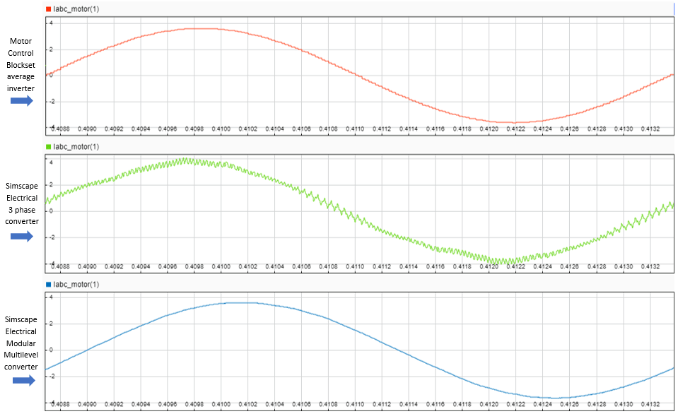
下图显示  相电流的仿真结果:
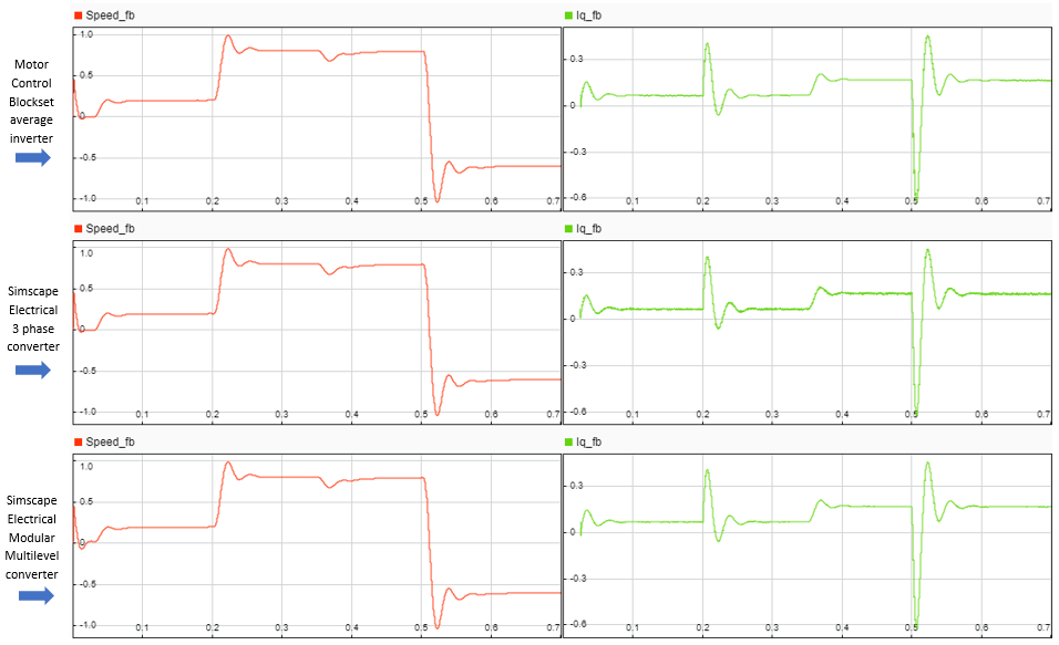
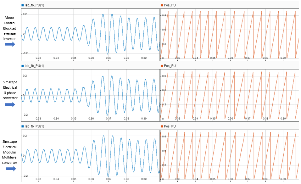
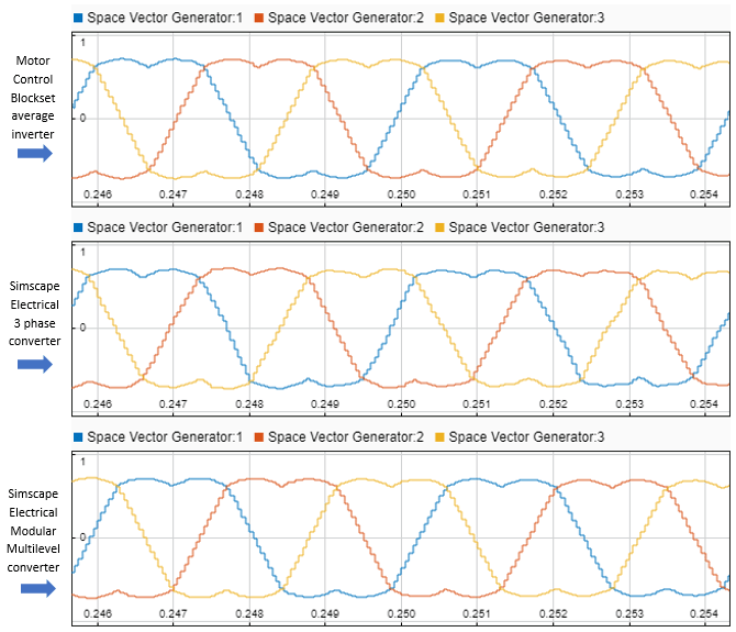
以下各图显示三种逆变器类型的转子转速、 电流、
电流、 相电流和转子位置的比较:
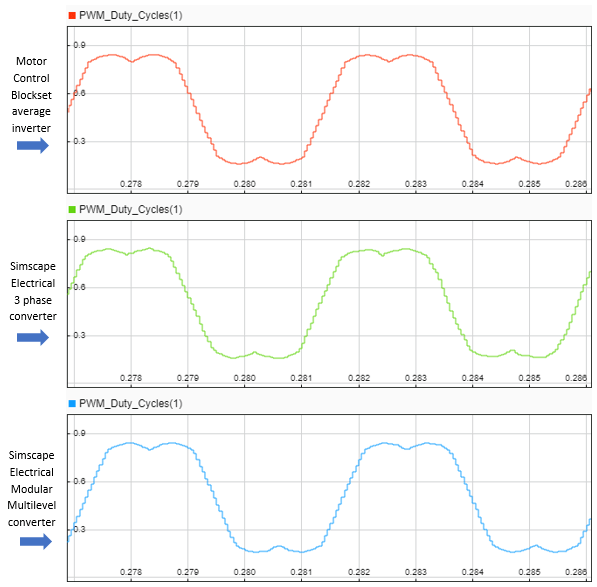
以下各图显示三种逆变器类型的 PWM 调制波形的比较:
生成代码并将模型部署到目标硬件
本节将指导您生成代码并在目标硬件上运行 FOC 算法。
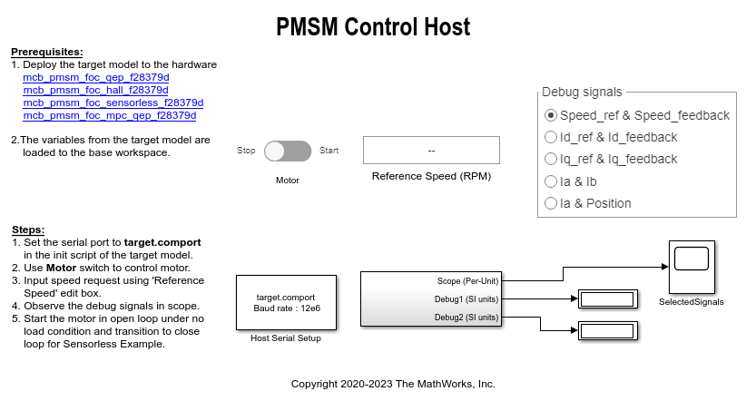
该示例使用一个主机模型和一个目标模型。主机模型是控制器硬件板的一个用户界面。您可以在主机上运行主机模型。使用主机模型的前提条件是将目标模型部署到控制器硬件板上。主机模型使用串行通信对目标 Simulink 模型发出指令,并以闭环控制方式运行电机。
必需的硬件
该示例支持以下硬件配置。您还可以在 MATLAB 命令提示符下使用目标模型名称打开对应硬件配置的模型。
LAUNCHXL-F28379D 控制器 + BOOSTXL-DRV8305 逆变器:
mcb_ee_pmsm_foc
有关与前述硬件配置相关的连接,请参阅 LAUNCHXL-F28069M 和 LAUNCHXL-F28379D 配置。
生成代码并在目标硬件上运行模型
1.仿真目标模型并观测仿真结果。
2.完成硬件连接。
3.该模型自动计算 ADC(或电流)偏移值。要禁用此功能(默认启用),请在模型初始化脚本中将变量 inverter.ADCOffsetCalibEnable 的值更新为 0。
您也可以计算 ADC 偏移值,并在模型初始化脚本中手动更新它。有关说明,请参阅以开环控制方式运行三相 AC 电机并校准 ADC 偏移量。
4.计算正交编码器索引偏移值,并在与目标模型相关联的模型初始化脚本中更新它。有关说明,请参阅 PMSM 的正交编码器偏移量校准。
5.打开目标模型。如果您要更改该模型的默认硬件配置设置,请参阅模型配置参数。
6.例如,为了确保 CPU2 没有错误地配置为使用预留给 CPU1 的板载外设,将一个示例程序加载到 LAUNCHXL-F28379D 的 CPU2(LAUNCHXL-F28379D 是使用 GPIO31 (c28379D_cpu2_blink.slx) 操作 CPU2 蓝色 LED 的程序)。有关示例程序或模型的详细信息,请参阅 Texas Instruments入门指南 C2000 Microcontroller Blockset (C2000 Microcontroller Blockset) 中的“任务 2 - 为 TI Delfino F28379D LaunchPad(双核)创建、配置和运行模型”部分。
7.点击硬件选项卡上的编译、部署和启动以将目标模型部署到硬件上。
8.点击目标模型中的 mcb_pmsm_foc_host_model_f28379d.slx 主机模型超链接以打开关联的主机模型。
有关主机模型和目标模型之间串行通信的详细信息,请参阅Host-Target Communication。
9.在与目标模型关联的模型初始化脚本中,使用变量 target.comport 指定通信端口。该示例使用此变量来更新主机模型中可用的 Host Serial Setup、Host Serial Receive 和 Host Serial Transmit 模块的端口参数。
10.更新主机模型中的参考转速值。
11.点击仿真选项卡上的运行以运行主机模型。
12.将 Start / Stop Motor 开关的位置切换到 On 以开始运行电机。
13.在主机模型的 Time Scope 和 Display 模块中,观测来自 RX 子系统的调试信号。
注意:在主机模型中,您还可以选择要监控的调试信号。
其他可尝试的操作
您还可以使用 SoC Blockset™ 来实现闭环电机控制应用,以应对与 ADC-PWM 同步、控制器响应和研究不同 PWM 设置相关的挑战。您可以使用 Simscape Electrical 来实现高保真度逆变器仿真。有关详细信息,请参阅Integrate MCU Scheduling and Peripherals in Motor Control Application。