DAC Testbench
Measure DC and AC performance metrics of DAC output

Libraries:
Mixed-Signal Blockset /
DAC /
Measurements & Testbenches
Description
The DAC Testbench block measures both DC and AC performance metrics of a DAC (digital to analog converter). DC performance metrics include offset error and gain error. AC performance metrics include signal-to-noise ratio (SNR), signal to noise and distortion radio (SINAD), spurious-free dynamic range (SFDR), effective number of bits (ENOB), and noise floor.
The DAC Testbench block generates the stimulus to drive the device under test (DUT) from the Stimulus tab. The setup parameters for validating the DUT are defined on the Setup tab. The target validation metrics are defined on the Target Metric tab.
You can use the DAC Testbench block to validate the DAC architecture models provided in Mixed-Signal Blockset™, or you can validate a DAC of your own implementation.
Examples
This example shows how to find the offset and gain errors of a binary weighted DAC block.
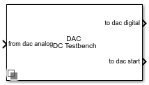
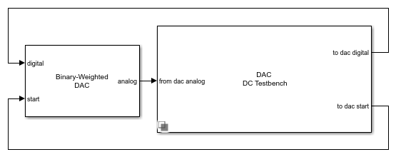
Open the model dac_dc_error
. The model consists of a Binary Weighted DAC block and a DAC Testbench.
model = 'dac_dc_error';
open_system(model)
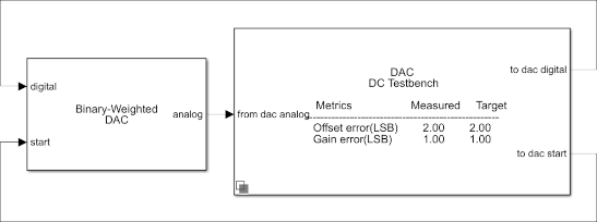
The parameters under the General tab of the Binary Weighted DAC are kept at their default values. The impairments are enabled in the Impairments tab, and the value of the offset error and gain error are set to 2
LSB and 1
LSB, respectively.
In the DAC Testbench block, the Measurement option is set to DC
. In the Setup tab, the Autofill setup parameter button is used to automatically propagate the setup parameters from the DAC block. In the Target Metric tab, the Autofill target metric button is used to automatically set the target offset and gain errors from the DAC block. All other parameters are kept at their default values.
Run the simulation for 7.68e-04
s. The measured offset and gain errors are 2.00
LSB and 1.00
LSB, respectively.
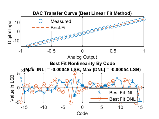
The DAC transfer curve matches the best linear fit method. Using best fit method, maximum INL is -3.3e-4
LSB and maximum DNL is 4.6e-4
LSB.
This example shows how to find the AC performance metrics such as SNR, SINAD, SFDR, ENOB, noise floor and settling time of a binary weighted DAC block.
Open the model dac_ac_error
. The model consists of a Binary Weighted DAC block and a DAC Testbench.
model = 'dac_ac_error';
open_system(model)
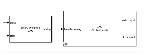
The parameters of the Binary Weighted DAC are kept at their default values.
In the DAC Testbench block, the Measurement option is set to AC
. In the Setup tab, the Autofill setup parameter button is used to automatically propagate the setup parameters from the DAC block. Show spectrum analyzer during simulation option is also checked.
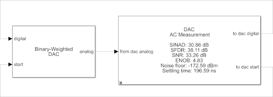
Run the simulation for 9e-3
s.
sim(model);
The measured AC performance metrics are displayed on the DAC Testbench block.
Ports
Input
Analog input signal from the DAC output, specified as a scalar.
Data Types: double
Output
Digital output stimulus signal for the DAC input, returned as a scalar.
Data Types: single
| double
| int8
| int16
| int32
| uint8
| uint16
| uint32
| fixed point
External start conversion clock for DAC, returned as a scalar. The rising edge of this signal starts the conversion process in the DAC block.
Data Types: double
Parameters
Select whether to measure static (DC) or dynamic (AC) performance metrics:
Select
DC
to measure offset error and gain error.Select
AC
to measure SNR, SINAD, SFDR, ENOB, and noise floor.
Minimum time for which the simulation must run to obtain meaningful results, specified as a positive real scalar in seconds.
To measure DC performance, the simulation must run so that the DAC can sample each digital code 20 times. Based on this assumption, the Recommended min. simulation stop time (s) T is given by:
,
where StartFreq is the frequency of the conversion-start clock and Nbits is the resolution of the DAC.
The number of samples per bit is calculated using the equation:
.
To measure AC performance, the simulation must run so that the DAC can generate six spectral updates of the DAC output. So, the Recommended min. simulation stop time (s) T is given by [1]:
,
where RBW is the resolution bandwidth of the spectrum estimator inside the DAC Testbench block and is given by the equation: .
This parameter is only reported by the testbench and is not editable.
Data Types: double
Click to automatically set the Recommended min. simulation stop time (s) as the stop time of the Simulink® model.
Measure the differential nonlinearity (DNL) error and integral nonlinearity (INL) error using the endpoint method. This method uses the endpoints of the actual transfer function to measure the DNL and INL errors.
Dependencies
To enable this parameter, set Measurement to
DC
.
Measure the differential nonlinearity (DNL) error and integral nonlinearity (INL) error using the best fit method. This method uses a standard curve-fitting technique to find the best fit to measure the DNL and INL errors.
Dependencies
To enable this parameter, set Measurement to
DC
.
Click to plot DC analysis result for further analysis. To perform a complete DC analysis including integral nonlinearity (INL) and differential nonlinearity (DNL), use the DAC DC Measurement block.
Dependencies
To enable this parameter, set Measurement to
DC
.
Click to store detailed test results to a spreadsheet (XLS file) or as comma-separated values (CSV file) for further processing.
Stimulus
Frequency of the digital input signal to the DAC block, specified as a positive real scalar in hertz. Digital input frequency (Hz) must match the input frequency of the DAC device under test.
Digital input frequency (Hz) needs to satisfy two requirements:
All the output codes of the DAC must be activated.
The Digital input frequency (Hz) must not share any common multiples other than 1 with the Start conversion frequency (Hz).
Dependencies
To enable this parameter, set Measurement to
AC
.
Programmatic Use
Block parameter:
InputFrequency |
Type: character vector |
Values: positive real scalar |
Default:
1e3 |
Data Types: double
Frequency of internal start-conversion clock, specified as a positive real scalar in Hz. Start conversion frequency (Hz) determines the rate of the DAC.
Programmatic Use
Block parameter:
StartFreq |
Type: character vector |
Values: positive real scalar |
Default:
1e6 |
Data Types: double
Maximum allowed difference in the amplitude of successive samples of the digital input signal, specified as a positive real scalar in least significant bit (LSB).
Dependencies
To enable this parameter, set Measurement to
DC
.
Programmatic Use
Block parameter:
ErrorTolerance |
Type: character vector |
Values: positive scalar in the range
(0, 1 ] |
Default:
0.1 |
Data Types: double
Setup
Click to automatically propagate setup parameters from the DAC.
Dependencies
The DAC must be a Binary Weighted DAC from the Mixed-Signal Blockset.
Number of bits in the input word, specified as a unitless positive real integer. Number of bits determines the resolution of the DAC.
Programmatic Use
Block parameter:
NBits |
Type: character vector |
Values: positive real integer |
Default:
10 |
Data Types: double
Polarity of the input signal to the DAC.
Programmatic Use
Block parameter:
Polarity |
Type: character vector |
Values:
Bipolar |Unipolar |
Default:
Bipolar |
Reference voltage of the DAC, specified as a real scalar in volts. Reference (V) helps determine the output from the input digital code, Number of bits, and Bias (V) using the equation:
.
Dependencies
To enable this parameter, set Measurement to
DC
.
Programmatic Use
Block parameter:
Ref |
Type: character vector |
Values: real scalar |
Default:
1 |
Data Types: double
Bias voltage added to the output of the DAC, specified as a real scalar in volts. Bias (V) helps determine the output from the input digital code, Number of bits, and Reference (V) using the equation:
Dependencies
To enable this parameter, set Measurement to
DC
.
Programmatic Use
Block parameter:
Bias |
Type: character vector |
Values: real scalar |
Default:
0 |
Data Types: double
The time required for the output of the DAC to settle to within some fraction of its final value, specified as a nonnegative real scalar in seconds.
Dependencies
To enable this parameter, set Measurement to
DC
.
Programmatic Use
Block parameter:
SettlingTime |
Type: character vector |
Values: real scalar |
Default:
0.25/1e-6 |
Data Types: double
The tolerance allowed for calculating settling time, specified as a positive real scalar in LSB. The output of the DAC must settle within the Settling time tolerance (LSB) by Settling time (s).
Dependencies
To enable this parameter, set Measurement to
AC
.
Programmatic Use
Block parameter:
SettlingTimeTolerance |
Type: character vector |
Values: positive real scalar |
Default:
0.5 |
Data Types: double
Delay before measurement analysis to avoid corruption by transients, specified as a nonnegative real scalar in seconds.
Programmatic Use
Use
get_param(gcb,'HoldOffTime')
to view the current value of Hold off time (s).Use
set_param(gcb,'HoldOffTime',value)
to set Hold off time (s) to a specific value.
Data Types: double
Select this parameter to display the Spectrum Analyzer window during simulation. By default, this parameter is deselected.
Dependencies
To enable this parameter, set Measurement to
AC
.
Target Metric
Click to automatically propagate target metrics from the DAC.
Dependencies
To enable this parameter, set Measurement to
DC
.The DAC must be a Binary Weighted DAC from the Mixed-Signal Blockset.
Shifts quantization steps by a specific value, specified as a real scalar in %FS (percentage of full scale), FS (full scale), or LSB (least significant bit).
Note
The full scale range of the converter is defined as the difference between the last and first code on the +0.5 LSB compensated transfer curve. In a +0.5 LSB compensated transfer curve, first code is 0.5 LSB wide while the last code is 1.5 LSB wide. The input values must be considered within the full scale range of the converter.
Note
LSB is calculated by the equation .
Dependencies
To enable this parameter, set Measurement to
DC
.
Programmatic Use
Block parameter:
TargetOffsetError |
Type: character vector |
Values: real scalar |
Default:
0 LSB |
Data Types: double
Error in the slope of the straight line interpolating the DAC transfer curve, specified as a real scalar in %FS (percentage of full scale), FS (full scale), or LSB (least significant bit).
Note
The full scale range of the converter is defined as the difference between the last and first code on the +0.5 LSB compensated transfer curve. In a +0.5 LSB compensated transfer curve, first code is 0.5 LSB wide while the last code is 1.5 LSB wide. The input values must be considered within the full scale range of the converter.
Note
LSB is calculated by the equation .
Dependencies
To enable this parameter, set Measurement to
DC
.
Programmatic Use
Programmatic Use
Block parameter:
TargetGainError |
Type: character vector |
Values: real scalar |
Default:
0 LSB |
Data Types: double
References
Version History
Introduced in R2020a
MATLAB Command
You clicked a link that corresponds to this MATLAB command:
Run the command by entering it in the MATLAB Command Window. Web browsers do not support MATLAB commands.
Select a Web Site
Choose a web site to get translated content where available and see local events and offers. Based on your location, we recommend that you select: .
You can also select a web site from the following list
How to Get Best Site Performance
Select the China site (in Chinese or English) for best site performance. Other MathWorks country sites are not optimized for visits from your location.
Americas
- América Latina (Español)
- Canada (English)
- United States (English)
Europe
- Belgium (English)
- Denmark (English)
- Deutschland (Deutsch)
- España (Español)
- Finland (English)
- France (Français)
- Ireland (English)
- Italia (Italiano)
- Luxembourg (English)
- Netherlands (English)
- Norway (English)
- Österreich (Deutsch)
- Portugal (English)
- Sweden (English)
- Switzerland
- United Kingdom (English)