Analyzing Simple ADC with Impairments
This example shows how to implement a basic ADC using a Zero-Order Hold block as a sampler. This simple ADC highlights some of the typical impairments introduced in an analog-to-digital converters such as aperture jitter, nonlinearity, quantization, and saturation. This example shows how to measure the effects of such impairments using a Spectrum Analyzer block and the ADC AC Measurement block from the Mixed-Signal Blockset™. To better approximate real-world performance, you can individually enable the impairments in the model.
model = 'MSADCImpairments';
open_system(model)
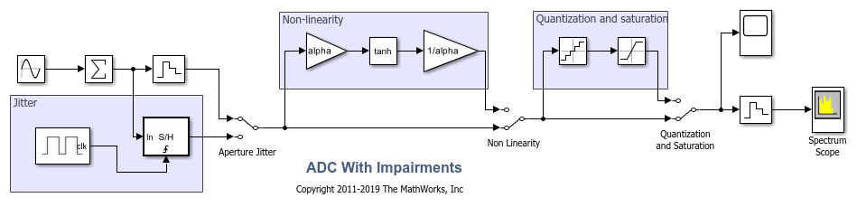
To observe the behavior of an ideal ADC, bypass the impairments using the switches. Set the Sine Wave source to generate two tones as an input signal.
set_param([model '/Aperture Jitter'],'sw','1');
set_param([model '/Non Linearity'],'sw','0');
set_param([model '/Quantization and Saturation'],'sw','0');
set_param([model '/Sine Wave'],'Frequency', '2*pi*[47 53]*1e6');
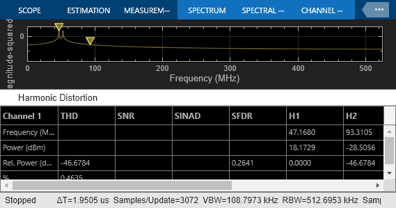
Simulate the model and observe the expected clean output spectrum of the ADC.
sim(model);
Effect of Aperture Jitter
Set the first switch to the down position. The Variable Delay block delays the signal sample-by-sample by the amount on its td input. The Noise Source block generates a uniform random variable, which is low-pass filtered by the Shape the jitter noise spectrum block before it arrives at the td input to the Variable Delay. Use a shaped uniform noise distribution to represent the jitter. Notice that in this model, the clock of the ADC is specified in the ideal zero-order hold block, and it is equal to 1/Fs, where Fs is a MATLAB® variable defined in the model initialization callback and equal to 1.024 GHz.
set_param([model '/Aperture Jitter'],'sw','0');
As expected, the spectrum degrades because of the presence of the jitter.
sim(model);

Effect of Nonlinearity
Set the second switch to the up position. This enables the ADC nonlinearity. A scaled hyperbolic tangent function provides nonlinearity. Its scale factor, alpha, determines the amount of nonlinearity the tanh applies to the signal. By default, alpha is 0.01.
set_param([model '/Non Linearity'],'sw','1');
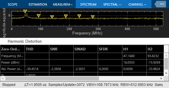
The spectrum degrades because of the nonlinearity as higher order harmonics get generated.
sim(model);

Effect of Quantization and Saturation
Set the third switch to the up position enabling the ADC quantization and hard saturation.
set_param([model '/Quantization and Saturation'],'sw','1');
The spectrum degrades because of the quantization effects. The noise floor raises as seen in the spectrum.
sim(model);
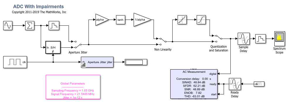
ADC AC Measurements
Use the ADC AC Measurement block in the Mixed-Signal Blockset™ to measure the noise performance of the ADC and compute the effective number of bits (ENOB).
Use single sinusoidal tone as input to the ADC to measure other metrics.
bdclose(model);
model = 'MSADCImpairments_AC';
open_system(model);
Ftest = 33/round(2*pi*2^8)*Fs;
set_param([model '/Sine Wave'],'Frequency', '2*pi*Ftest');

scopecfg = get_param([model '/Spectrum Scope'], 'ScopeConfiguration');
scopecfg.DistortionMeasurements.Algorithm = 'Harmonic';
scopecfg.FFTLength = '512';
scopecfg.WindowLength = '512';

sim(model);
riseFallSpec =

  Group with properties:

              Name: 'RiseFallBox'
            Prompt: 'Rise/Fall Time'
               Row: 'new'
           Enabled: 'off'
           Visible: 'off'
      AlignPrompts: 'off'
    DialogControls: [1x7 Simulink.dialog.Control]
           Tooltip: ''


riseFallSpec =

  Group with properties:

              Name: 'RiseFallBox'
            Prompt: 'Rise/Fall Time'
               Row: 'new'
           Enabled: 'off'
           Visible: 'off'
      AlignPrompts: 'off'
    DialogControls: [1x7 Simulink.dialog.Control]
           Tooltip: ''
The Aperture Jitter Measurement block from Mixed-Signal Blockset™ measures the average jitter introduced on the signal to be approximately equal to 1 ps. Delay is added
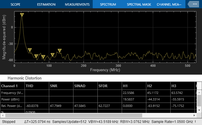
Additionally, use the spectrum analyzer to measure:
Output Third Order Intercept Point (OIP3)
Signal to Noise Ratio (SNR)
Total Harmonic Distortion (THD)
Increase the factor alpha to increase the nonlinearity of the ADC and make the effects of nonlinearity more evident on top of the noise floor. This is just for demonstration purposes.
alpha = 0.8;
Use a two tone test signal as input to the ADC for the intermodulation measurements.
set_param([model '/Sine Wave'],'Frequency', '2*pi*[50e6 75e6]');
To enable distortion measurements in the spectrum analyzer, click on Distortion Measurement as in the figure below and select Intermodulation as Distortion type.
scopecfg.DistortionMeasurements.Algorithm = 'Intermodulation';
scopecfg.FFTLength = '4096';
scopecfg.WindowLength = '4096';

sim(model);
riseFallSpec =

  Group with properties:

              Name: 'RiseFallBox'
            Prompt: 'Rise/Fall Time'
               Row: 'new'
           Enabled: 'off'
           Visible: 'off'
      AlignPrompts: 'off'
    DialogControls: [1x7 Simulink.dialog.Control]
           Tooltip: ''
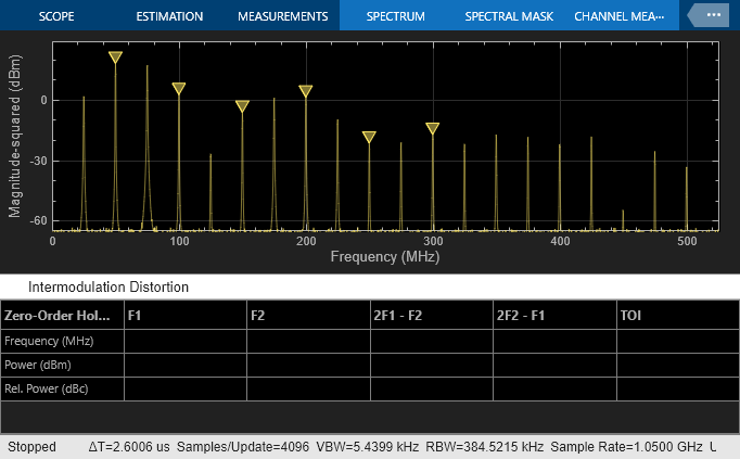
The scope allows for the measurement of the third order products adjacent to the input signals, and determines the output referred third order intercept point.
See Also
Sampling Clock Source | Aperture Jitter Measurement | ADC AC Measurement