Effect of Surface-to-Surface Radiation on Battery Module Under Thermal Runaway Condition
This example shows how to include surface-to-surface radiation effects in thermal analysis of a battery module. The example analyzes a 18650 Li-ion battery module consisting of nine cells, connectors at both ends, and the casing. The space between the cells and the casing is free space, and any conductive heat transfer due to stagnant air is ignored. The example accounts for heat exchange due to conduction through material and radiation between surfaces. The conduction heat transfer path consists of components in thermal contact. Radiated heat exchange between components not in thermal contact becomes significant at higher temperatures, such as in thermal runaway conditions. The example simulates a thermal runaway scenario by imposing a large heat generation load on one of the cells in the module.
This example uses SI units of measurement. The results show temperature distributions with and without surface-to-surface radiation.
Thermal Analysis Model
Create a battery module geometry consisting of nine cells, connectors at both ends, and the casing by running the following command. For details about creating the geometry, see the Battery Module Geometry example.
run("batteryModuleGeometryCreation.mlx");Create an femodel object for thermal transient analysis and include the geometry.
model = femodel(AnalysisType="thermalTransient", ...
                Geometry=gmAssembled);
Specify the thermal conductivity, mass density, and specific heat of the material for the battery module cells. The cells have orthotropic thermal conductivity, with a large axial thermal conductivity of 14 W/(K*m) and a small radial thermal conductivity of 2 W/(K*m).
model.MaterialProperties(domainIDs.Cells) = ...
    materialProperties(ThermalConductivity=[2,2,14], ...
                       MassDensity=2500, ...
                       SpecificHeat=1000);
This battery module has connectors made of copper and a casing made of aluminum. Assign the corresponding thermal material properties to the relevant cells.
model.MaterialProperties(domainIDs.Connector) = ...
    materialProperties(ThermalConductivity=400, ...
                       MassDensity=8960, ...
                       SpecificHeat=385);
model.MaterialProperties(domainIDs.Casing) = ...
    materialProperties(ThermalConductivity=205, ...
                       MassDensity=2700, ...
                       SpecificHeat=900);
Find the cells adjacent to the cell and casing boundaries to get more control over mesh generation near these boundaries and to define the surface-to-surface radiation enclosure. To find faces forming these boundaries, use the referencePoints structure returned as a result of the geometry creation file, batteryModuleGeometryCreation.mlx. See Battery Module Geometry for details.
cellBoundaries = ...
    nearestFace(gmAssembled,referencePoints.Cell)
cellBoundaries = 1×9
1 4 7 10 13 16 19 22 25
casingBoundaries = ...
    [nearestFace(gmAssembled,...
                 [referencePoints.Casing;...
                 [0,0,-cellLength/2- ...
                 connectorThickness-casingThickness];...
                 [0,0, cellLength/2+ ...
                 connectorThickness+casingThickness]])]
casingBoundaries = 1×6

    93    88    92    86    75    82
To get a reasonable mesh while saving time, generate a mesh using the Hface argument.
model = generateMesh(model, ...
    Hface={cellBoundaries,0.005,casingBoundaries,0.05});
Assign an initial room temperature of 293 K. Because this analysis includes radiation, use an absolute temperature.
model.CellIC = cellIC(Temperature=293);
Specify the cell ID of the trigger cell, which is the cell going into thermal runaway and generating a large amount of heat. In this geometry, cells have IDs 1 through 9. In the top view, cell 1 is at the bottom-left corner, and cell 9 is at the top-right corner. Cell 5 is at the center of the module. In this analysis, cell 1 is assumed to be the trigger cell.
triggerCell = 1;
Apply the heat load. To create a thermal runaway scenario, apply a nominal heat generation of 3 W on all cells except the trigger cell.
volumeCell = pi*(cellDiameter)^2/4*cellLength;
model.CellLoad(setdiff(1:9,triggerCell)) = ...
    cellLoad(Heat=3/volumeCell);
Apply a heat generation of 60 W on the trigger cell.
model.CellLoad(triggerCell) = ...
    cellLoad(Heat=60/volumeCell);
Radiation heat transfer analysis requires the Stefan-Boltzmann constant. The toolbox has no default value for the Stefan-Boltzmann constant because its value depends on the system of units. Specify the constant in the SI system of units.
model.StefanBoltzmann = 5.670367E-8;
Solution Without Surface-to-Surface Radiation
First, solve the model not including surface-to-surface radiation.
tlist = 0:10:300;
tic
RnoRad = solve(model,tlist);
toc
Elapsed time is 8.551442 seconds.
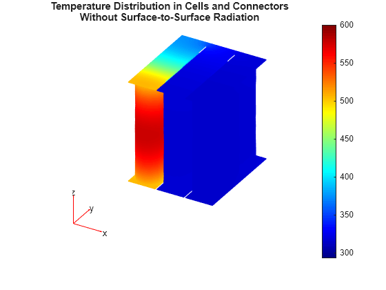
Plot the temperature distribution in the cells and connectors. The conduction path provided by the connectors causes the heat to flow from the trigger cell to all cells. To see the battery module's interior, find the elements forming the cells and connectors, and plot only those elements.
elemCellTabs = ...
    findElements(model.Mesh, ...
                 "region", ...
                 Cell=[domainIDs.Cells,domainIDs.Connector]);
figure
pdeplot3D(model.Mesh.Nodes, ...
          model.Mesh.Elements(:,elemCellTabs), ...
          ColorMapData=RnoRad.Temperature(:,end))
title({"Temperature Distribution in Cells and Connectors"; ...
       "Without Surface-to-Surface Radiation"})
clim([293,600]);

Solution with Surface-to-Surface Radiation
Next, include the inter-cell radiation effect by setting up the surface-to-surface radiation model. Define a radiation enclosure comprising the inner boundaries of the cells and casing.
enclusreFaces = [cellBoundaries casingBoundaries];
Use the Monte Carlo method to compute view factors between the mesh facets in the enclosure faces.
model = setupRadiation(model, ...
                       EnclosureFaces=enclusreFaces, ...
                       ViewFactorMethod="montecarlo");
Assign an emissivity of 0.9 to all enclosure faces.
model.FaceLoad(enclusreFaces) = faceLoad(Emissivity=0.9);
Solve the model including surface-to-surface radiation.
RRad = solve(model,tlist);
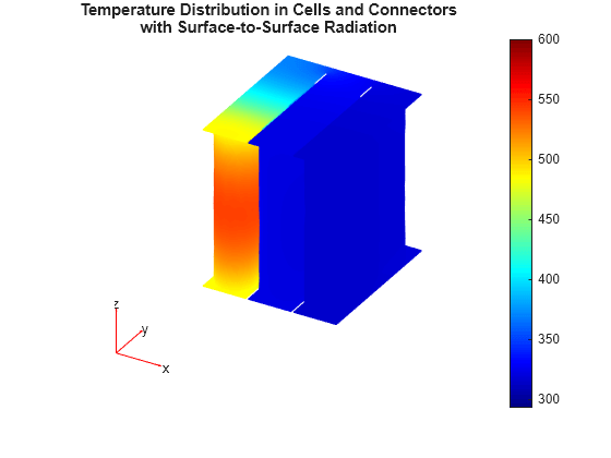
Plot the solution. The maximum temperature on the trigger cell is lower than in the previous solution because radiation, in addition to conduction, transfers heat away from the cell.
figure
pdeplot3D(model.Mesh.Nodes, ...
          model.Mesh.Elements(:,elemCellTabs), ...
          ColorMapData=RRad.Temperature(:,end))
title({"Temperature Distribution in Cells and Connectors";
       "with Surface-to-Surface Radiation"})
clim([293,600])

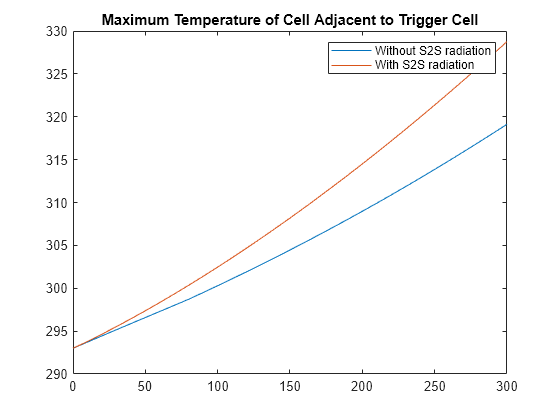
To show the effect of including surface-to-surface radiation on a cell adjacent to the trigger cell, plot the maximum temperature on cell 4. Note that cell 4 is in the next column of cells and is far away in terms of the conductive path.
NodesAdjacentCell = findNodes(model.Mesh,"region",Cell=4);
MaxTempCell4NoRadiation = max(RnoRad.Temperature(NodesAdjacentCell,:));
MaxTempCell4WithRadiation = max(RRad.Temperature(NodesAdjacentCell,:));
figure
plot(tlist,MaxTempCell4NoRadiation,tlist,MaxTempCell4WithRadiation);
legend("Without S2S radiation", "With S2S radiation");
title("Maximum Temperature of Cell Adjacent to Trigger Cell")

You can see the same effect by plotting the spatial temperature distribution on cell 4 alone for the final time step. Note the circumferential variation of the temperature when surface-to-surface radiation is included.
elemsCell4 = findElements(model.Mesh, ...
                          "region", ...
                          Cell=4);
figure
tiledlayout(1,2)
ax1 = nexttile;
pdeplot3D(model.Mesh.Nodes, ...
          model.Mesh.Elements(:,elemsCell4), ...
          ColorMapData=RnoRad.Temperature(:,end))
title(ax1,"Without Surface-to-Surface Radiation");
clim([300,330])
ax2 = nexttile;
pdeplot3D(model.Mesh.Nodes, ...
          model.Mesh.Elements(:,elemsCell4), ...
          ColorMapData=RRad.Temperature(:,end))
title(ax2,"With Surface-to-Surface Radiation");
clim([300,330])
