Finite Element Analysis of Electrostatically Actuated MEMS Device
This example shows a simple approach to the coupled electromechanical finite element analysis of an electrostatically actuated micro-electromechanical (MEMS) device. For simplicity, this example uses the relaxation-based algorithm rather than the Newton method to couple the electrostatic and mechanical domains.
MEMS Devices
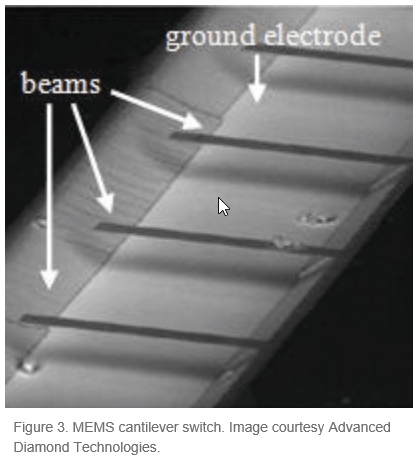
MEMS devices typically consist of movable thin beams or electrodes with a high aspect ratio that are suspended over a fixed electrode.

Actuation, switching, and other signal and information processing functions can use the electrode deformation caused by the application of voltage between the movable and fixed electrodes. FEM provides a convenient tool for characterizing the inner workings of MEMS devices, and can predict temperatures, stresses, dynamic response characteristics, and possible failure mechanisms. One of the most common MEMS switches is the series of cantilever beams suspended over a ground electrode.
This example uses the following geometry to model a MEMS switch. The top electrode is 150 μm in length and 2 μm in thickness. Young’s modulus E is 170 GPa, and Poisson’s ratio υ is 0.34. The bottom electrode is 50 μm in length and 2 μm in thickness, and is located 100 μm from the leftmost end of the top electrode. The gap between the top and bottom electrodes is 2 μm.

A voltage applied between the top electrode and the ground plane induces electrostatic charges on the surface of the conductors, which in turn leads to electrostatic forces acting normal to the surface of the conductors. Because the ground plane is fixed, the electrostatic forces deform only the top electrode. When the beam deforms, the charge redistributes on the surface of the conductors. The resultant electrostatic forces and the deformation of the beam also change. This process continues until the system reaches a state of equilibrium.
Approach for Coupled Electromechanical Analysis
For simplicity, this example uses the relaxation-based algorithm rather than the Newton method to couple the electrostatic and mechanical domains. The example follows these steps:
1. Solve the electrostatic FEA problem in the nondeformed geometry with the constant potential V0 on the movable electrode.
2. Compute the load and boundary conditions for the mechanical solution by using the calculated values of the charge density along the movable electrode. The electrostatic pressure on the movable electrode is given by
,
where is the magnitude of the electric flux density and is the electric permittivity next to the movable electrode.
3. Compute the deformation of the movable electrode by solving the mechanical FEA problem.
4. Update the charge density along the movable electrode by using the calculated displacement of the movable electrode,
where is the magnitude of the electric flux density in the deformed electrode, is the magnitude of the electric flux density in the undeformed electrode, is the distance between the movable and fixed electrodes in the absence of actuation, and is the displacement of the movable electrode at position x along its axis.
5. Repeat steps 2–4 until the electrode deformation values in the last two iterations converge.
Electrostatic Analysis
In the electrostatic analysis part of this example, compute the electric potential around the electrodes.
First, create the cantilever switch geometry by using the constructive solid geometry (CSG) modeling approach. The geometry for electrostatic analysis consists of three rectangles represented by a matrix. Each column of the matrix describes a basic shape.
rect_domain = [3 4 1.75e-4 1.75e-4 -1.75e-4 -1.75e-4 ...
                  -1.7e-5 1.3e-5 1.3e-5 -1.7e-5]';
rect_movable = [3 4 7.5e-5 7.5e-5 -7.5e-5 -7.5e-5 ...
                    2.0e-6 4.0e-6 4.0e-6 2.0e-6]';
rect_fixed = [3 4 7.5e-5 7.5e-5 2.5e-5 2.5e-5 -2.0e-6 0 0 -2.0e-6]';
gd = [rect_domain,rect_movable,rect_fixed];
Create a name for each basic shape. Specify the names as a matrix whose columns contain the names of the corresponding columns in the basic shape matrix.
ns = char('rect_domain','rect_movable','rect_fixed');
ns = ns';
Create a formula describing the unions and intersections of the basic shapes.
sf = 'rect_domain-(rect_movable+rect_fixed)';Create the geometry by using the decsg function.
g = decsg(gd,sf,ns);
Plot the geometry.
pdegplot(g,EdgeLabels="on",FaceLabels="on")
xlabel("x-coordinate, meters")
ylabel("y-coordinate, meters")
axis([-2e-4,2e-4,-4e-5,4e-5])
axis square
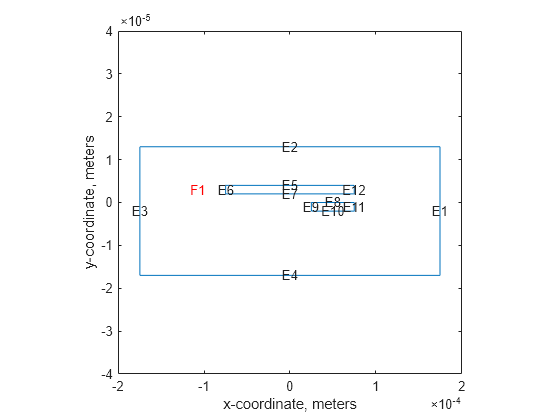
The edge numbers in this geometry are:
Movable electrode: E5, E6, E7, E12
Fixed electrode: E8, E9, E10, E11
Domain boundary: E1, E2, E3, E4
Create an femodel object for electrostatic analysis and include the geometry in the model.
model = femodel(AnalysisType="electrostatic", ...
                Geometry=g);
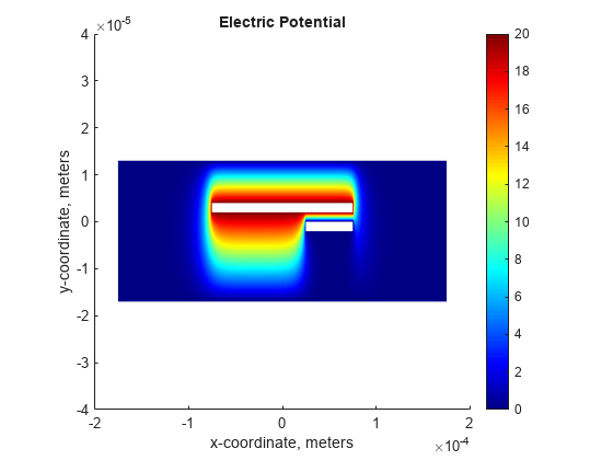
Set constant potential values of 20 V to the movable electrode and 0 V to the fixed electrode and domain boundary.
V0 = 0;
V1 = 20;
model.EdgeBC([1:4 8:11]) = edgeBC(Voltage=0);
model.EdgeBC([5:7 12]) = edgeBC(Voltage=20);
Specify the vacuum permittivity value in the SI system of units.
model.VacuumPermittivity = 8.8541878128e-12;
Specify the relative permittivity of the material.
model.MaterialProperties = ...
        materialProperties(RelativePermittivity=1);
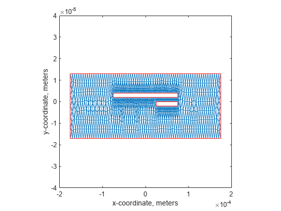
Generate a relatively fine mesh.
model = generateMesh(model,Hmax=5e-6);
pdemesh(model)
xlabel("x-coordinate, meters")
ylabel("y-coordinate, meters")
Solve the model.
results = solve(model);
Plot the electric potential in the exterior domain.
u = results.ElectricPotential;
figure
pdeplot(results.Mesh,XYData=results.ElectricPotential, ...
                     ColorMap="jet");

title("Electric Potential");
xlabel("x-coordinate, meters")
ylabel("y-coordinate, meters")
axis([-2e-4,2e-4,-4e-5,4e-5])
axis square
You also can plot the electric potential in the exterior domain by using the Visualize PDE Results Live Editor task. First, create a new live script by clicking the New Live Script button in the File section on the Home tab.

On the Live Editor tab, select Task > Visualize PDE Results. This action inserts the task into your script.
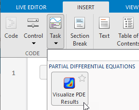
To plot the electric potential, follow these steps.
In the Select results section of the task, select
resultsfrom the drop-down list.In the Specify data parameters section of the task, set Type to Nodal solution.

Mechanical Analysis
In the mechanical analysis part of this example, compute the deformation of the movable electrode.
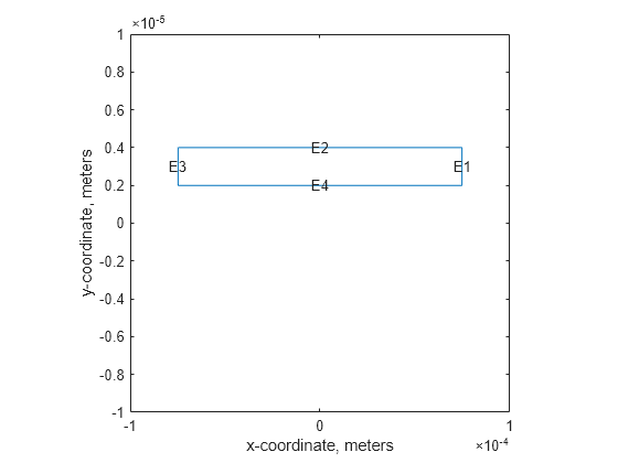
Create and plot the movable electrode geometry.
g = decsg(rect_movable);
pdegplot(g,EdgeLabels="on")
xlabel("x-coordinate, meters")
ylabel("y-coordinate, meters")
axis([-1e-4,1e-4,-1e-5,1e-5])
axis square
Create an femodel object for static structural analysis and include the geometry into the model.
model = femodel(AnalysisType="structuralStatic", ...
                Geometry=g);
Specify the structural properties: Young's modulus is 170 GPa and Poisson's ratio is 0.34.
model.MaterialProperties = ...
    materialProperties(YoungsModulus=170e9, ...
                       PoissonsRatio=0.34);
Specify the pressure as a boundary load on the edges. The pressure tends to draw the conductor into the field regardless of the sign of the surface charge. For the definition of the CalculateElectrostaticPressure function, see Electrostatic Pressure Function.
pressureFcn = @(location,state) - ...
              CalculateElectrostaticPressure(results,[],location);
model.EdgeLoad([1 2 4]) = edgeLoad(Pressure=pressureFcn);
Specify that the movable electrode is fixed at edge 3.
model.EdgeBC(3) = edgeBC(Constraint="fixed");Generate a mesh.
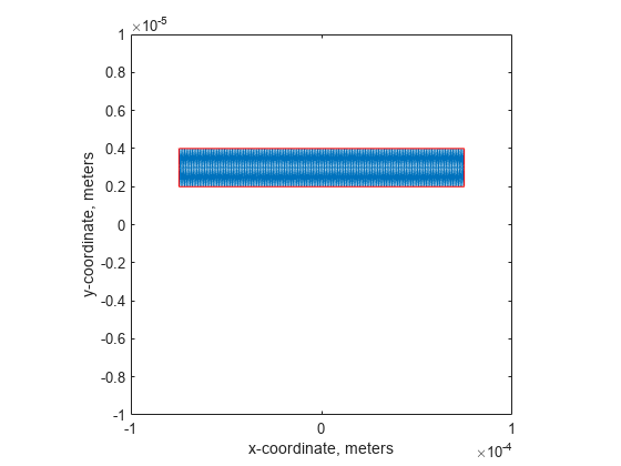
model = generateMesh(model,Hmax=1e-6);
pdemesh(model);
xlabel("x-coordinate, meters")
ylabel("y-coordinate, meters")
axis([-1e-4, 1e-4,-1e-5, 1e-5])
axis square
Solve the equations.
R = solve(model);
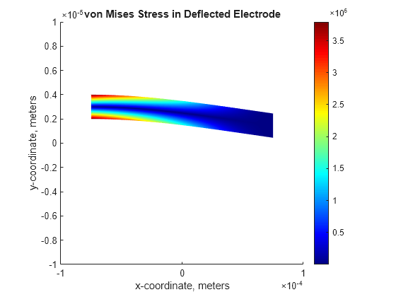
Plot the displacement for the movable electrode.
pdeplot(R.Mesh,XYData=R.VonMisesStress, ...
        Deformation=R.Displacement, ...
        DeformationScaleFactor=10, ...
        ColorMap="jet");

title("von Mises Stress in Deflected Electrode")
xlabel("x-coordinate, meters")
ylabel("y-coordinate, meters")
axis([-1e-4,1e-4,-1e-5,1e-5])
axis square
Find the maximal displacement.
maxdisp = max(abs(R.Displacement.uy));
fprintf('Finite element maximal tip deflection is: %12.4e\n', ...
         maxdisp);
Finite element maximal tip deflection is: 1.5504e-07
Repeatedly update the charge density along the movable electrode and solve the model until the electrode deformation values converge.
olddisp = 0;
while abs((maxdisp-olddisp)/maxdisp) > 1e-10
% Impose boundary conditions
  pressureFcn = @(location,state) - ...
                CalculateElectrostaticPressure(results,R,location);
  model.EdgeLoad([1 2 4]) = edgeLoad(Pressure=pressureFcn);
% Solve the equations
    R = solve(model);
    olddisp = maxdisp;
    maxdisp = max(abs(R.Displacement.uy));
end
Plot the displacement.
pdeplot(R.Mesh,XYData=R.VonMisesStress, ...
        Deformation=R.Displacement, ...
        DeformationScaleFactor=10, ...
        ColorMap="jet");

title("von Mises Stress in Deflected Electrode")
xlabel("x-coordinate, meters")
ylabel("y-coordinate, meters")
axis([-1e-4,1e-4,-1e-5,1e-5])
axis square

Find the maximal displacement.
maxdisp = max(abs(R.Displacement.uy));
fprintf('Finite element maximal tip deflection is: %12.4e\n', maxdisp);
Finite element maximal tip deflection is: 1.7994e-07
References
[1] Sumant, P. S., N. R. Aluru, and A. C. Cangellaris. “A Methodology for Fast Finite Element Modeling of Electrostatically Actuated MEMS.” International Journal for Numerical Methods in Engineering. Vol 77, Number 13, 2009, 1789-1808.
Electrostatic Pressure Function
The electrostatic pressure on the movable electrode is given by
,
where is the magnitude of the electric flux density, is the electric permittivity next to the movable electrode, and is the magnitude of the electric field. The electric field is the gradient of the electric potential :
.
Solve the mechanical FEA to compute the deformation of the movable electrode. Using the calculated displacement of the movable electrode, update the charge density along the movable electrode.
where is the magnitude of the electric flux density in the deformed electrode, is the magnitude of the electric flux density in the undeformed electrode, is the distance between the movable and fixed electrodes in the absence of actuation, and is the displacement of the movable electrode at position x along its axis. Initially, the movable electrode is undeformed, , and therefore, .
function ePressure = ...
 CalculateElectrostaticPressure(elecResults,structResults,location)
% Function to compute electrostatic pressure.
% structuralBoundaryLoad is used to specify
% the pressure load on the movable electrode.
% Inputs:
% elecResults: Electrostatic FEA results
% structResults: Mechanical FEA results (optional)
% location: The x,y coordinate
% where pressure is obtained
%
% Output:
% ePressure: Electrostatic pressure at location
%
% location.x : The x-coordinate of the points
% location.y : The y-coordinate of the points
xq = location.x;
yq = location.y;

% Compute the magnitude of the electric field
% from the potential difference.
Eintrp = interpolateElectricField(elecResults,xq,yq);
absE = sqrt(Eintrp.Ex'.^2 + Eintrp.Ey'.^2);

% The permittivity of vacuum is 8.854*10^-12 farad/meter.
epsilon0 = 8.854e-12;

% Compute the magnitude of the electric flux density.
absD0 = epsilon0*absE;
absD = absD0;

% If structResults (deformation) is available,
% update the charge density along the movable electrode.
if ~isempty(structResults)
 % Displacement of the movable electrode at position x
 intrpDisp = interpolateDisplacement(structResults,xq,yq);
 vdisp = abs(intrpDisp.uy');
 G = 2e-6; % Gap 2 micron
 absD = absD0.*G./(G-vdisp);
end

% Compute the electrostatic pressure.
ePressure = absD.^2/(2*epsilon0);

end
