phased.UnderwaterRadiatedNoise
Radiate acoustic noise from underwater or surface sound source
Description
The phased.UnderwaterRadiatedNoise System object™ creates a source of underwater radiated acoustic noise. The noise source can either be on the sea surface or underwater. The radiated noise consists of two components: broadband noise and tonal noise. Broadband noise fills the entire operating system bandwidth while tonal noise occurs at discrete frequencies within the bandwidth. In general, the intensity of the radiated noise depends on the noise spectrum and the source radiation pattern. The object lets you specify
The spectral shape and levels of the broadband noise.
The frequencies and levels of the tones.
The noise source radiation pattern.
To propagate noise from a source to a receiver, use this object with the
phased.IsoSpeedUnderwaterPaths and the phased.MultipathChannel objects.
To generate radiated underwater noise:
Create the
phased.UnderwaterRadiatedNoiseobject and set its properties.Call the object with arguments, as if it were a function.
To learn more about how System objects work, see What Are System Objects?
Creation
Syntax
Description
noiseradiator = phased.UnderwaterRadiatedNoise
noiseradiator = phased.UnderwaterRadiatedNoise(Name,Value)Name
set to a specified Value. You can specify additional name-value pair
arguments in any order as
(Name1,Value1,...,NameN,ValueN).
Enclose each property name in single quotes.
Example: noiseradiator = phased.UnderwaterRadiatedNoise('TonalLevels',[4700
4900 5150],'SampleRate',500,'OperatingFrequency',5000) creates a noise source
with tones at 4.7, 4.9, and 5.15 kHz. The sample rate is set to 0.5 kHz and the operating
frequency is 5 kHz. The broadband noise levels are set to default values.
Properties
Usage
Syntax
Input Arguments
Output Arguments
Object Functions
To use an object function, specify the
System object as the first input argument. For
example, to release system resources of a System object named obj, use
this syntax:
release(obj)
The reset object function resets the random number generator state
when the SeedSource
property is set to 'Property'.
Examples
Generate radiated noise from a surface ship. The sonar operating frequency is 5.0 kHz and the sampling rate is 1.0 kHz. By definition, broadband noise band lies in the band 4.5 kHz to 5.5 kHz. In addition, there are tonal noises at 4.6, 5.2, and 5.4 kHz.
shippos = [0;0;0];
rcvpos = [100;0;-50];
Compute the noise transmission angle from the ship to the receiver.
[~,ang] = rangeangle(rcvpos,shippos)
ang = 2×1

         0
  -26.5651
Construct a phased.UnderwaterRadiatedNoise System object™ having a radiation pattern that depends only on elevation angle. Compute the noise radiated in the direction of the receiver. Create 10000 samples of the noise radiated towards the target.
azang = [-180:180];
elang = [-80:80];
pattern = mag2db(repmat(cosd(elang)',1,numel(azang)));
fs = 1000;
noiseradiator = phased.UnderwaterRadiatedNoise('NumSamples',10000, ...
    'SampleRate',fs,'TonalFrequencies',[4600 5200 5400],'TonalLevels',[200,200,200], ...
    'BroadbandLevels',[180 180 190 190 190 188 185],'AzimuthAngles',azang, ...
    'ElevationAngles',elang,'DirectionalPattern',pattern, ...
    'OperatingFrequency',5e3,'SeedSource','Property','Seed',2781);
Generate 10000 samples of noise.
y = noiseradiator(ang);
Plot the noise power spectral density (psd). Convert the psd to intensity referenced to 1uPa.
[psd,fr] = pwelch(y,[],[],[],noiseradiator.SampleRate,'psd','centered');
plot(fr,10*log10(psd*1e12));
title('Power Spectral Density')
xlabel('frequency (Hz)')
ylabel('PSD //dB/Hz/1uPa')
grid
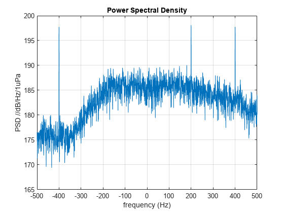
The three tones appear over the broadband spectrum.
Generate radiated noise from an underwater vehicle. Assume that the noise radiation pattern depends on frequency. The sonar operating frequency is 5.0 kHz and the sampling rate is 1.0 kHz. By definition, the broadband noise band is from 4.5 kHz to 5.5 kHz. In addition, there are tonal noises at 4.6, 5.2, and 5.3 kHz. Define the radiation pattern at three frequencies within this band. All three patterns are multiples of the basic pattern. The frequencies of the radiation patterns are 4.6 kHz, 5.0 kHz, and 5.3 kHz.
First, specify the source and receiver positions.
srcpos = [0;50;-20];
rcvpos = [100;0;-50];
Compute the noise transmission angle from vehicle to receiver.
[~,ang] = rangeangle(rcvpos,srcpos)
ang = 2×1

  -26.5651
  -15.0203
Construct a phased.UnderwaterRadiatedNoise System object™ with a radiation pattern that depends only on the azimuth angle and frequency. Compute the noise radiated in the direction of the receiver. Create 10000 samples of noise radiated from the vehicle.
azang = [-180:180];
elang = [-90:90];
fc = 5000.0;
Put the radiation pattern in a three-dimensional array.
basepattern = repmat(10*cosd(azang).^2,numel(elang),1);
pattern(:,:,1) = 0.5*basepattern;
pattern(:,:,2) = basepattern;
pattern(:,:,3) = 0.6*basepattern;
patterndb = mag2db(pattern);
noiseradiator = phased.UnderwaterRadiatedNoise('NumSamples',10000, ...
    'SampleRate',1e3,'TonalFrequencies',[4600,5200 5300], ...
    'TonalLevels',[200,210,200],'BroadbandLevels',[180 180 190 190 190 180 170], ...
    'AzimuthAngles',azang,'ElevationAngles',elang, ...
    'FrequencyVector',[4600,5000,5300],'DirectionalPattern',pattern, ...
    'OperatingFrequency',5e3,'SeedSource','Property','Seed',2081);
Generate 10000 samples of noise.
y = noiseradiator(ang);
Plot the noise power spectral density (psd). Convert the psd to intensity referenced to 1uPa.
[psd,fr] = pwelch(y,[],[],[],noiseradiator.SampleRate,'psd','centered');
plot(fr,10*log10(psd*1e12));
title('Power Spectral Density')
xlabel('frequency (Hz)')
ylabel('PSD //dB/Hz/1uPa')
grid
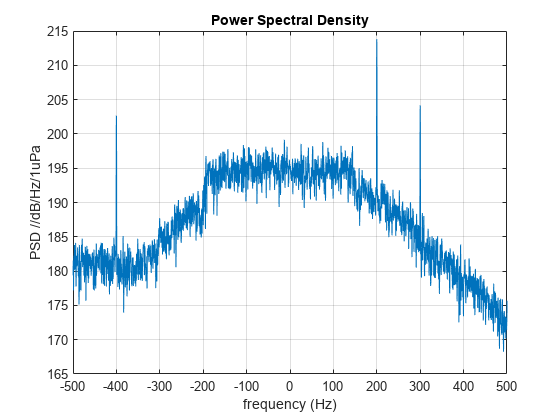
The three tones appear over the broadband spectrum.
Generate radiated noise from a two underwater vehicles. Assume that the noise radiation pattern is different for each. The sonar operating frequency is 5.0 kHz and the sampling rate is 1.0 kHz. By definition, the broadband noise band is from 4.5 kHz to 5.5 kHz. In addition, there are tonal noises at 4.6, 5.2, and 5.3 kHz. The frequencies of the radiation patterns are 4.6 kHz, 5.0 kHz, and 5.3 kHz.
First, specify the source and receiver positions.
srcpos1 = [0;50;-20];
srcpos2 = [200;50;-80];
rcvpos = [100;0;-50];
Compute the noise transmission angle from vehicle to receiver.
[~,ang1] = rangeangle(rcvpos,srcpos1);
[~,ang2] = rangeangle(rcvpos,srcpos2);
Construct a phased.UnderwaterRadiatedNoise System object™ with a radiation pattern that depends only on the azimuth angle and frequency. Compute the noise radiated in the direction of the receiver. Create 10000 samples of noise radiated from the vehicle.
azang = [-180:180];
elang = [-90:90];
fc = 5000.0;
Put the radiation pattern in a three-dimensional array.
pattern1 = repmat(10*cosd(azang).^2,numel(elang),1);
pattern2 = ones(181,361);
pattern1db = mag2db(pattern1);
pattern2db = mag2db(pattern2);
noiseradiator = phased.UnderwaterRadiatedNoise('NumSamples',10000, ...
    'SampleRate',1e3,'TonalFrequencies',[4600,5200 5300], ...
    'TonalLevels',[200,210,200],'BroadbandLevels',[180 180 190 190 190 180 170], ...
    'AzimuthAngles',azang,'ElevationAngles',elang, ...
    'FrequencyVector',[4600,5000,5300],'DirectionalPattern',{pattern1,pattern2}, ...
    'OperatingFrequency',5e3,'SeedSource','Property','Seed',2081);
Generate 10000 samples of noise.
y = noiseradiator([ang1,ang2]);
Plot the noise power spectral density (psd). Convert the psd to intensity referenced to 1uPa.
[psd,fr] = pwelch(y,[],[],[],noiseradiator.SampleRate,'psd','centered');
plot(fr,10*log10(psd*1e12));
title('Power Spectral Density')
xlabel('frequency (Hz)')
ylabel('PSD //dB/Hz/1uPa')
grid
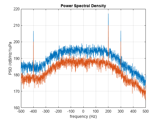
The three tones appear over the broadband spectrum.
More About
References
[1] Urick, R.J. Principles of Underwater Sound, 3rd Edition. New York: Peninsula Publishing, 1996.
Extended Capabilities
Version History
Introduced in R2017b
See Also
Objects
phased.BackscatterSonarTarget|phased.IsoSpeedUnderwaterPaths|phased.IsotropicHydrophone|phased.IsotropicProjector|phased.MultipathChannel
Functions
range2tl|sonareqsl|sonareqsnr|sonareqtl|tl2range