Main Content

rotpat

Rotate radiation pattern

Description

example

rpat = rotpat(pat,az,el,rotax) rotates a radiation pattern, pat, into a new pattern, rpat, whose boresight is aligned with the x-axis of a new local coordinate system defined by rotax. az and el specify the azimuth and elevation angles at which the original pattern is sampled.

rpat = rotpat(pat,az,el,rotax,expval) also specifies an extrapolated value to be used when az and el do not cover the entire 3-D space.

Tip

You can use this function to rotate real and complex scalar radiation patterns as well as the orthogonal components of polarized fields. To rotate polarized fields, rotate the horizontal and vertical polarization components separately.

Examples

collapse all

Use a short-dipole antenna to create a polarized radiation pattern. Rotate the pattern and use the rotated pattern as the radiation pattern of a custom antenna.

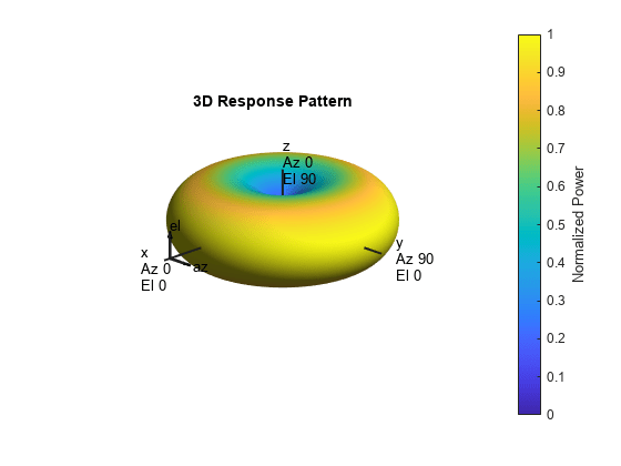
Create a phased.ShortDipoleAntennaElement antenna object with default properties. The short-dipole antenna radiates polarized radiation. Obtain and display the radiation for all directions.

antenna1 = phased.ShortDipoleAntennaElement;
el = -90:90;
az = -180:180;
pat_h = zeros(numel(el),numel(az),'like',1+1i);
pat_v = pat_h;
fc = 3e8;
for m = 1:numel(el)
    temp = antenna1(fc,[az;el(m)*ones(1,numel(az))]);
    pat_h(m,:) = temp.H;
    pat_v(m,:) = temp.V;
end
pattern(antenna1,fc,'Type','Power')

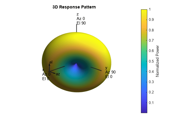
Rotate the antenna pattern around the y-axis by 135 degrees followed by a rotation around the x-axis by 65 degrees.

newax = rotx(65)*roty(135);
pat2_h = rotpat(pat_h,az,el,newax);
pat2_v = rotpat(pat_v,az,el,newax);

Insert the rotated pattern into a phased.CustomAntennaElement object. Set the antenna polarization properties so that the element radiates horizontal and vertical polarized fields. Then display the rotated pattern in three dimensions.

antenna2 = phased.CustomAntennaElement( ...
    'SpecifyPolarizationPattern',true, ...
    'HorizontalMagnitudePattern',mag2db(abs(pat2_h)), ...
    'HorizontalPhasePattern',rad2deg(angle(pat2_h)), ...
    'VerticalMagnitudePattern',mag2db(abs(pat2_v)), ...
    'VerticalPhasePattern',rad2deg(angle(pat2_v)));
pattern(antenna2,fc,'Type','Power')

Create a radiation pattern for a cosine antenna using a phased.CosineAntennaElement object. Rotate the pattern to use in a phased.CustomAntennaElement antenna object.

First obtain the radiation pattern for a phased.CosineAntennaElement object over a limited range of directions. The field is not polarized.

antenna1 = phased.CosineAntennaElement('CosinePower',[5,5]);
az = -60:65;
el = -60:60;
pat = zeros(numel(el),numel(az),'like',1);
fc = 300e6;
for m = 1:numel(el)
    temp = antenna1(fc,[az;el(m)*ones(1,numel(az))]);
    pat(m,:) = temp;
end

Display the original pattern.

imagesc(az,el,abs(pat))
axis xy
axis equal
axis tight
xlabel('Azimuth (deg)')
ylabel('Elevation (deg)')
title('Original Radiation Pattern')
colorbar

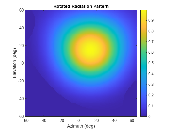
Rotate the antenna pattern by 20 degrees around the z-axis and 50 degrees around the x-axis. Then display the rotated pattern.

newax = rotx(50)*rotz(20);
rpat = rotpat(pat,az,el,newax);
imagesc(az,el,abs(rpat))
axis xy
axis equal
axis tight
xlabel('Azimuth (deg)')
ylabel('Elevation (deg)')
title('Rotated Radiation Pattern')
colorbar

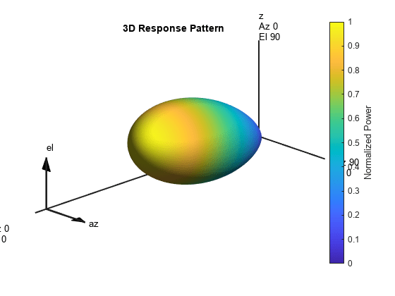
Use the rotated pattern in a custom antenna element and display the pattern in 3-D.

antenna2 = phased.CustomAntennaElement( ...
    'AzimuthAngles',az,'ElevationAngles',el,'SpecifyPolarizationPattern',false, ...
    'MagnitudePattern',mag2db(abs(rpat)), ...
    'PhasePattern',zeros(size(rpat)));
pattern(antenna2,fc,'Type','Power')

Input Arguments

collapse all

Radiation pattern, specified as a complex-valued N-by-M matrix or complex-valued N-by-M-by-L array. N is the length of the el vector and M is the length of the az vector. Each column corresponds to one of the azimuth angles specified in the az argument. Each row corresponds to one of the elevation angles specified in the el argument. You can specify multiple radiation patterns using L pages. For example, you can use pages to specify radiation patterns at different frequencies. The main lobe of each pattern is assumed to point along the x-axis. Units are in meters-squared.

Data Types: double
Complex Number Support: Yes

Azimuth angles for computing 3-D radiation pattern, specified as a 1-by-M real-valued row vector where M is the number of azimuth angles. Each entry corresponds to one of the columns of the matrix specified in the pat argument. Angle units are in degrees. Azimuth angles must lie between –180° and 180°, inclusive.

The azimuth angle is the angle between the x-axis and the projection of the direction vector onto the xy-plane. The azimuth angle is positive when measured from the x-axis toward the y-axis.

Example: -45:2:45

Data Types: double

Elevation angles for computing directivity and pattern, specified as a 1-by-N real-valued row vector where N is the number of elevation angles. Each entry corresponds to one of the rows of the matrix specified in the pat argument. Angle units are in degrees. Elevation angles must lie between –90° and 90°, inclusive.

The elevation angle is the angle between the direction vector and xy-plane. The elevation angle is positive when measured toward the z-axis.

Example: -75:1:70

Data Types: double

Rotation matrix, specified as a real-valued orthonormal 3-by-3 matrix or a real-valued 3-by-3-by-P array. The columns represent the x, y, and z directions of the rotated coordinate system with respect to the original coordinate system. The P pages specify different rotation matrices.

This table describes how dimensions of the output pattern rpat depend on the dimensions of the pat and rotax arguments.

Dimensions of rpat

Dimensions of patDimensions of rotax
 3-by-33-by-3-by-P
M-by-NRotate a single pattern by a single rotation matrix. Output dimensions of rpat are M-by-N.Rotate a single pattern by P different rotation matrices. Output dimensions of rpat are M-by-N-by-P.
M-by-N-by-LRotate L patterns by the same rotation matrix. Output dimensions of rpat are M-by-N-by-L.In this case, P must equal L and the function rotates each pattern by the corresponding rotation matrix. Output dimensions of rpat are M-by-N-by-L.

Example: rotx(45)*roty(30)

Data Types: double

Extrapolation value, specified as a scalar. This scalar is the extrapolated value when the rotated patterns do not fill the entire 3-D space specified by az and el. In general, consider setting expval to 0 if the pattern is specified in a linear scale or -inf if the pattern is specified in a dB scale.

Example: -inf

Data Types: double

Output Arguments

collapse all

Rotated radiation pattern, returned as a complex-valued N-by-M matrix or complex-valued N-by-M-by-P array. N is the length of the el vector. M is the length of the az vector. The dimensionality of pat and rotax determine the value of P as discussed in the rotax input argument. Units are in meters-squared.

Data Types: double
Complex Number Support: Yes

Extended Capabilities

C/C++ Code Generation
Generate C and C++ code using MATLAB® Coder™.

Version History

Introduced in R2019a

See Also

| |