Modeling RF Front End in Radar System Simulation
In a radar system, the RF front end often plays an important role in defining the system performance. For example, because the RF front end is the first section in the receiver chain, the design of its low noise amplifier is critical to achieving the desired signal to noise ratio (SNR). This example shows how to incorporate RF front end behavior into an existing radar system design.
This example requires RF Blockset™.
Available Example Implementations
This example includes two Simulink® models:
Monostatic Radar with One Target: slexMonostaticRadarRFExample.slx
FMCW Radar Range and Speed Estimation: slexFMCWRFExample.slx
Introduction
Several examples, such as Simulating Test Signals for a Radar Receiver in Simulink and Automotive Adaptive Cruise Control Using FMCW and MFSK Technology (Radar Toolbox) have shown that one can build end-to-end radar systems in Simulink using Phased Array System Toolbox™. In many cases, once the system model is built, the next step could be adding more fidelity in different components. A popular candidate for such a component is the RF front end. One advantage of modeling the system in Simulink is the capability of performing multidomain simulations.
The following sections show two examples of incorporating RF Blockset modeling capability in radar systems built with Phased Array System Toolbox.
Monostatic Radar with One Target
The first model is adapted from example Simulating Test Signals for a Radar Receiver in Simulink which simulates a monostatic pulse radar with one target. From the diagram itself, the model below looks identical to the model shown in that example.
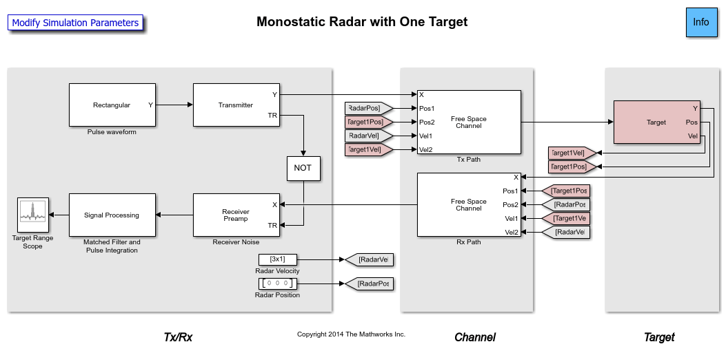
When the model is executed, the resulting plot is also the same.
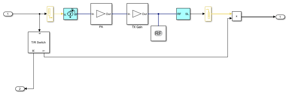
However, a deeper look in the transmitter subsystem shows that now the transmitter is modeled by power amplifiers from RF Blockset.
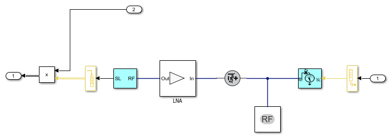
Similar changes are also implemented in the receiver side.
With these changes, the model is capable of simulating RF behaviors. For example, the simulation result shown above assumes a perfect power amplifier. In real applications, the amplifier will suffer many nonlinearities. If one sets the IP3 of the transmitter to 70 dB and runs the simulation again, the peak corresponding to the target is no longer as dominant. This gives the engineer some knowledge regarding the system's performance under different situations.
FMCW Radar Range and Speed Estimation
The second example is adapted from Automotive Adaptive Cruise Control Using FMCW and MFSK Technology (Radar Toolbox). However, this model uses a triangle sweep waveform instead so the system can estimate range and speed simultaneously. At the top level, the model is similar to what gets built from Phased Array System Toolbox. Once executed, the model shows the estimated range and speed values that matches the distance and relative speed of the target car.
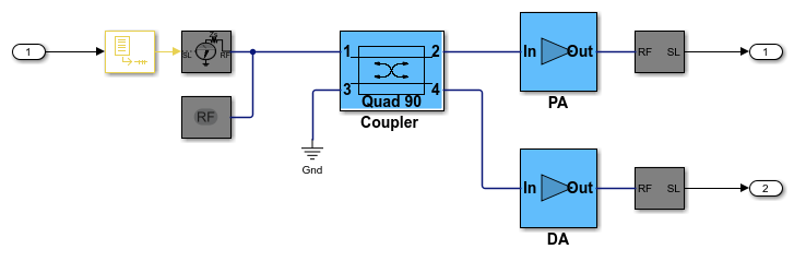
However, similar to the first example, the transmitter and receiver subsystems are now built with RF Blockset blocks.
The following figure shows the transmitter subsystem.
The following figure shows the receiver subsystem.
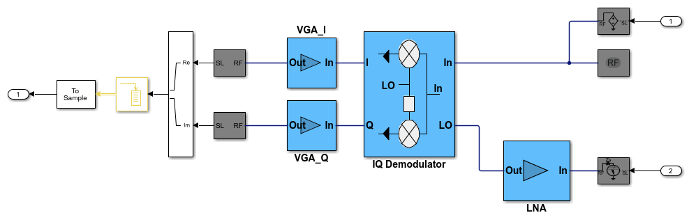
In a continuous wave radar system, part of the transmitted waveform is used as a reference to dechirp the received target echo. From the diagrams above, one can see that the transmitted waveform is sent to the receiver via a coupler and the dechirp is performed via an I/Q demodulator. Therefore, by adjusting parameters in those RF components, higher simulation fidelity can be achieved.
Summary
This example shows two radar models that are originally built with Phased Array System Toolbox and later incorporated RF models from RF Blockset. The simulation fidelity is greatly improved by combining the two products together.