Prepare Model for Structured Text Generation
To generate structured text code from Simulink® models, Stateflow® charts, and MATLAB® functions, use the Simulink PLC Coder™ product. Prepare your model for structured text code generation by performing action such as setting the solver, identifying if your model is a single rate or multirate model, and checking model compatibility for structured text code generation.
Tasking Mode
If your Simulink model contains multirate signals, you must set the tasking mode. If your Simulink model does not contain multirate signals, proceed to solver selection.
Simulink PLC Coder generates code for single-tasking subsystems. For multirate subsystems, you must first explicitly set the tasking mode to single-tasking before selecting a solver. In the model configuration, on the Solver pane, clear the check box for Treat each discrete rate as a separate task.
Choose a Solver
Choose a solver for your Simulink PLC Coder model.
| Model | Solver Setting |
|---|---|
| Variable-step | Use a continuous solver. Configure a fixed sample time for the subsystem for which you generate code. |
| Fixed-step | Use a discrete fixed-step solver. |
Configure Simulink Models for Structured Text Code Generation
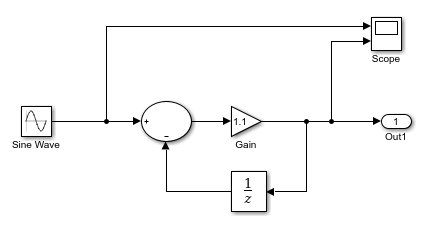
This tutorial uses the example model
plcdemo_simple_subsyystem.
In the Command Window, enter the model name to open the model.
openExample('plcdemo_simple_subsystem');
Configure the model to use the fixed-step discrete solver. Click the solver link in the lower-right corner of the model window. In the Solver information pane, click View solver settings to open the Solver pane of the model configuration parameters. Under the Solver selection, set Type to
Fixed-stepand Solver todiscrete (no continuous states).If your model uses a continuous solver and has a subsystem, configure a fixed sample time for the subsystem for which you generate code.
Save this model as
plcdemo_simple_subsystem1.Create a subsystem containing the components for which you want to generate structured text code.

Optionally, rename
In1andOut1toUandYrespectively, resulting in a subsystem like the following figure:
Save the model with the new subsystem.
In the top-level model, right-click the Subsystem block and select Block Parameters (Subsystem).
In the Block Parameters block dialog box, select Treat as atomic unit.
Click OK.
Simulate, and then save your model.
You can now:
Set up your subsystem to generate structured text code. See Verify System Compatibility for Structured Text Code Generation.
Generate structured text code for your IDE. See Generate and Examine Structured Text Code.
Verify System Compatibility for Structured Text Code Generation
You must already have a model configured to work with the Simulink PLC Coder software. If not, see Prepare Model for Structured Text Generation
In your model, navigate to the subsystem for which you want to generate code.
Click the subsystem block and in theApps tab, click PLC Coder. In the PLC Code tab, click Model Advisor. In the Model Advisor window , select all the Simulink PLC Coder checks, and click Run Checks.
If the subsystem is not atomic, right-click the subsystem block and select PLC Code > Enable “Treat as atomic unit” to generate code.

In the block parameter dialog box, select Treat as atomic unit.
Generate structured text code for your IDE. See Generate and Examine Structured Text Code.