Factor Graph-Based Lidar-Inertial Odometry
R2026bThis example shows how to estimate a trajectory using lidar-inertial odometry based on factor graph optimization.
Lidar-inertial odometry fuses geometric constraints from point cloud registration with inertial measurements from an IMU. Lidar provides accurate spatial structure but operates at a low frame rate. The IMU provides high-rate motion estimates that bridge the gap between lidar frames and improve robustness during aggressive maneuvers. By jointly optimizing both sources in a factor graph, the system produces trajectories that are more accurate and consistent than either sensor alone.
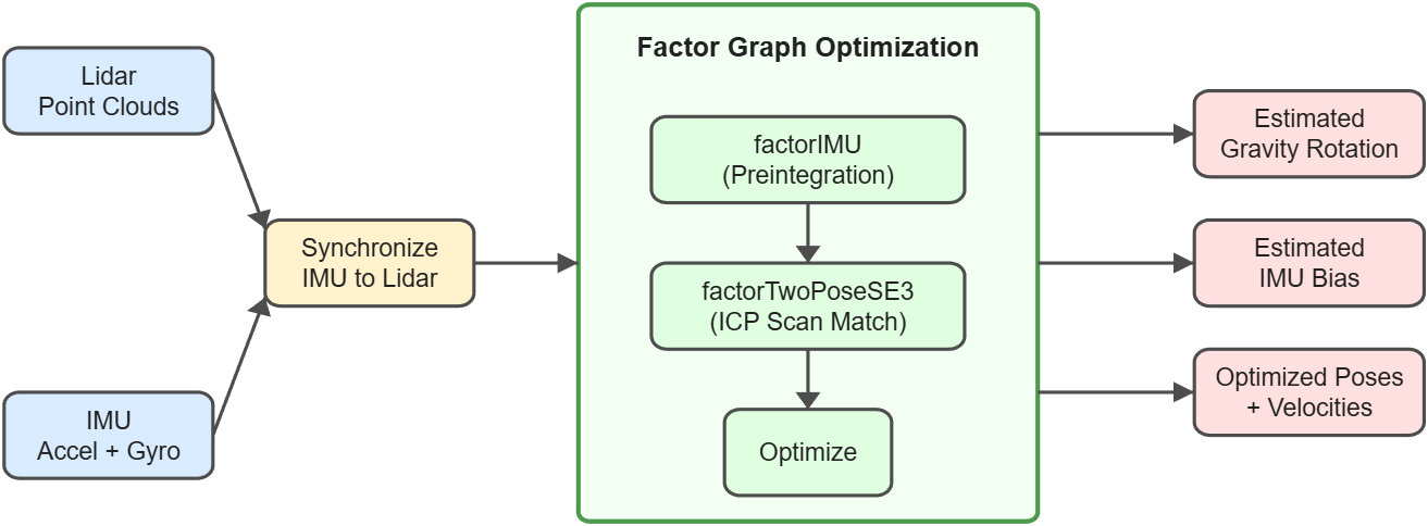
In this example, you learn how to:
Synchronize point cloud and IMU measurements by grouping high-rate inertial readings to each lidar frame.
Estimate the gravity rotation and IMU biases from a static initialization phase.
Build a factor graph that couples lidar point cloud registration and IMU preintegration constraints to jointly optimize poses, velocities, and IMU biases.
Compare the lidar-inertial trajectory against GPS ground truth.
Load and Read Sensor Data
The MUN-FRL dataset provides hardware-synchronized data from a Velodyne VLP-16 lidar, an Xsens MTi-30 IMU, and an RTK-GNSS receiver. The data was collected from a drone flying over outdoor environments including a lighthouse location. RTK-GNSS post-processed kinematic positioning provides ground truth for benchmarking. Download the rosbag and extract sensor streams using helperDownloadAndExtractMUNFRLData. The function downloads the rosbag if needed, extracts lidar point clouds, IMU accelerometer and gyroscope readings, and GPS fix positions.
dataFolder = fullfile(tempdir, "MUN-FRL-Lighthouse");

[lidarData, imuData, gpsData] = helperDownloadAndExtractMUNFRLData(dataFolder);
numFrames = numel(lidarData.Times);
Synchronize Sensor Data
The IMU operates at 400 Hz and the lidar at 10 Hz, yielding approximately 40 inertial measurements per lidar frame. Group the gyroscope and accelerometer readings by lidar timestamp so that downstream processing can access all IMU data between consecutive scans. Also convert the GPS latitude, longitude, and altitude to local ENU coordinates and interpolate to lidar timestamps for trajectory evaluation.
[gyroSync, accelSync, gpsENU] = helperSyncSensorsToLidar(imuData, gpsData, lidarData.Times);
Lidar-Inertial Odometry via Factor Graph
Formulate lidar-inertial odometry as a factor graph optimization problem. The graph fuses two complementary sources of motion information. Each factorIMU (Navigation Toolbox) preintegrates all IMU measurements between consecutive lidar frames, providing high-rate motion constraints. Each factorTwoPoseSE3 (Navigation Toolbox) encodes the relative transform from pcregistericp scan matching between those same frames, correcting drift with geometric alignment. The solver simultaneously optimizes all poses, velocities, and biases, allowing IMU preintegration and point cloud registration to inform each other.
The odometry proceeds in two phases using a single factor graph. First, process lidar frames within a static initialization window to jointly estimate the gravity rotation and IMU biases. Then, continue processing the remaining frames with the refined estimates.
To fuse lidar and IMU measurements, load the multi-sensor calibration parameters saved from the Create Multi-Sensor System from Pairwise Calibrations Using MUN-FRL Dataset (Computer Vision Toolbox) example. The SensorTransform parameter in factorIMU specifies the lidar-to-IMU extrinsics so that all pose nodes remain in the lidar frame while the factor correctly accounts for the IMU mounting offset.
msParams = load("multiSensorMUNFRL.mat").msp;

% Lidar-to-IMU extrinsics
tformLidarToIMU = transformation(msParams, "Lidar", "IMU");

% IMU noise parameters including calibrated noise and bias covariances
imuParams = intrinsics(msParams, "IMU");

% Set the random seed for reproducibility
rng(0);

% Registration parameters
distanceRange = [1.5 40];
icpGridStep = 0.5;
frameSkip = 10;
Set the information matrix weights for each factor type. The information matrix is the inverse of the covariance; higher values express more trust in that measurement.
Variable | Value | Notes |
| 1e6 | Anchors the coordinate frame origin since absolute position is unobservable |
| 1 | Allows the optimizer to refine orientation using IMU gravity alignment and subsequent measurements |
| 1e3 | Moderate trust in the initial zero velocity |
| 100 | Moderate prior assuming the bias is initially near zero |
| 100 | Trust in ICP point cloud registration relative transformations |
posePriorInfoTranslation = 1e6;
posePriorInfoRotation = 1;
velPriorInfo = 1e3;
biasPriorInfo = 100;
icpInfo = 100;
Create the factor graph and initialize the first node. The platform is stationary at startup, so estimate the gravity rotation from the static accelerometer readings and derive the initial lidar pose by composing the gravity rotation with the lidar-to-IMU extrinsic. Anchor the first pose, velocity, and bias nodes with prior factors.
startFrame = find(lidarData.Times > imuData.Times(1), 1, "first");
numInitFrames = 40;

G = factorGraph;
poseIdx = 1;
velIdx = 2;
biasIdx = 3;
gravityNodeID = generateNodeID(G, 1);
currNodeIDs = generateNodeID(G, 3); % [pose, vel, bias]

% Estimate gravity rotation from static accelerometer data
initAccel = mean(accelSync{startFrame}, 1);
measGravDir = initAccel / norm(initAccel);
refGravDir = [0 0 1];
gravAxis = cross(measGravDir, refGravDir);
gravAngle = acos(dot(measGravDir, refGravDir));
initGravSE3 = se3([gravAxis gravAngle], "axang");
gravState = xyzquat(initGravSE3);
initGravityState = gravState(4:7);

% Derive initial lidar pose from gravity rotation and lidar-to-IMU extrinsic
initLidarSE3 = initGravSE3 * se3(tformLidarToIMU);
firstPose = xyzquat(initLidarSE3);
estBias = zeros(1, 6);

% Add prior factors
fPosePrior = factorPoseSE3Prior(currNodeIDs(poseIdx), ...
    Measurement=firstPose, Information=diag([posePriorInfoTranslation*ones(1,3) posePriorInfoRotation*ones(1,3)]));
fVelPrior = factorVelocity3Prior(currNodeIDs(velIdx), ...
    Measurement=[0 0 0], Information=velPriorInfo*eye(3));
fBiasPrior = factorIMUBiasPrior(currNodeIDs(biasIdx), ...
    Measurement=estBias, Information=biasPriorInfo*eye(6));
addFactor(G, fPosePrior);
addFactor(G, fVelPrior);
addFactor(G, fBiasPrior);

nodeState(G, currNodeIDs(poseIdx), firstPose);
nodeState(G, currNodeIDs(velIdx), [0 0 0]);
nodeState(G, currNodeIDs(biasIdx), estBias);

prevPose = firstPose;
prevVel = [0 0 0];
imuBias = estBias;
iPrev = startFrame;
Estimate Gravity Rotation and IMU Bias
To use IMU data for navigation, the solver must know the gravity direction and the sensor biases. During the static initialization window, the accelerometer senses only gravity and the gyroscope reflects only bias. Add identity relative pose constraints between consecutive frames to encode the zero-motion assumption. Together with the IMU preintegration factors, these constraints give the solver enough information to separate gravity from bias.
lastInitFrame = min(startFrame + numInitFrames - 1, numFrames);

initFrameIndices = startFrame:frameSkip:lastInitFrame;
numInitSteps = numel(initFrameIndices);
numMainSteps = numel((initFrameIndices(end) + frameSkip):frameSkip:numFrames);
numTotalSteps = numInitSteps + numMainSteps;
poseNodeIDs = zeros(numTotalSteps, 1);
poseNodeIDs(1) = currNodeIDs(poseIdx);
viewID = 1;

% Identity measurement for stationary platform (no translation or rotation)
identityMeasurement = xyzquat(se3());

for i = (startFrame + frameSkip):frameSkip:lastInitFrame
    viewID = viewID + 1;

    prevNodeIDs = currNodeIDs;
    currNodeIDs = generateNodeID(G, 3);

    % IMU factor with SensorTransform to keep poses in lidar frame
    gyro = vertcat(gyroSync{iPrev+1:i});
    accel = vertcat(accelSync{iPrev+1:i});
    fIMU = factorIMU([prevNodeIDs, currNodeIDs, gravityNodeID], ...
        gyro, accel, imuParams, SensorTransform=se3(tformLidarToIMU));
    [predPose, predVel] = predict(fIMU, prevPose, prevVel, imuBias);
    addFactor(G, fIMU);

    % Initialize gravity node after it is created by the first IMU factor
    if viewID == 2
        nodeState(G, gravityNodeID, initGravityState);
    end

    nodeState(G, currNodeIDs(poseIdx), predPose);
    nodeState(G, currNodeIDs(velIdx), predVel);
    nodeState(G, currNodeIDs(biasIdx), imuBias);

    % Identity relative pose (platform is stationary)
    addFactor(G, factorTwoPoseSE3([prevNodeIDs(poseIdx), currNodeIDs(poseIdx)], ...
        Measurement=identityMeasurement, Information=1e4*eye(6)));

    poseNodeIDs(viewID) = currNodeIDs(poseIdx);
    prevPose = predPose;
    prevVel = predVel;
    iPrev = i;
end

% Optimize to estimate gravity rotation and refine IMU bias
optimize(G);

% Update state estimates with optimized values
prevPose = nodeState(G, currNodeIDs(poseIdx));
prevVel = nodeState(G, currNodeIDs(velIdx));
imuBias = nodeState(G, currNodeIDs(biasIdx));
Process Remaining Frames
Continue adding factors to the same graph for the remaining lidar frames. Before registration, use findPointsInCylinder to keep only points between 1.5 m and 40 m, removing self-returns from the drone body and noisy returns at the sensor limit, then downsample with a grid filter. Register consecutive frames with pcregistericp using the IMU-predicted relative pose as the initial guess. Call optimize (Navigation Toolbox) periodically to keep state estimates current.
prevPtCloud = helperPreprocessPointCloud(lidarData.PointClouds(iPrev), distanceRange, icpGridStep);

regFrameIndices = (iPrev + frameSkip):frameSkip:numFrames;
optimInterval = 5;

for i = regFrameIndices
    viewID = viewID + 1;
    currCloud = lidarData.PointClouds(i);

    % Advance node IDs
    prevNodeIDs = currNodeIDs;
    currNodeIDs = generateNodeID(G, 3);

    % Create IMU factor with SensorTransform to keep poses in lidar frame
    gyro = vertcat(gyroSync{iPrev+1:i});
    accel = vertcat(accelSync{iPrev+1:i});
    imuNodeIDs = [prevNodeIDs, currNodeIDs, gravityNodeID];
    fIMU = factorIMU(imuNodeIDs, gyro, accel, imuParams, ...
        SensorTransform=se3(tformLidarToIMU));
    [predPose, predVel] = predict(fIMU, prevPose, prevVel, imuBias);
    addFactor(G, fIMU);

    % Set node states using IMU prediction
    nodeState(G, currNodeIDs(poseIdx), predPose);
    nodeState(G, currNodeIDs(velIdx), predVel);
    nodeState(G, currNodeIDs(biasIdx), imuBias);

    % Register using IMU-predicted relative pose (already in lidar frame)
    prevSE3 = se3(prevPose, "xyzquat");
    predSE3 = se3(predPose, "xyzquat");
    initGuess = rigidtform3d(tform(prevSE3 \ predSE3));

    currPtCloud = helperPreprocessPointCloud(currCloud, distanceRange, icpGridStep);
    icpRelPose = pcregistericp(currPtCloud, prevPtCloud, ...
        InitialTransform=initGuess, Metric="planeToPlane");

    % Create lidar registration factor (poses are in lidar frame)
    fLidar = factorTwoPoseSE3([prevNodeIDs(poseIdx), currNodeIDs(poseIdx)], ...
        Measurement=xyzquat(se3(icpRelPose)), ...
        Information=icpInfo*eye(6));
    addFactor(G, fLidar);

    % Optimize periodically
    if mod(viewID, optimInterval) == 0 || i==regFrameIndices(end)
        optimize(G);
    end

    % Update state estimates
    prevPose = nodeState(G, currNodeIDs(poseIdx));
    prevVel = nodeState(G, currNodeIDs(velIdx));
    imuBias = nodeState(G, currNodeIDs(biasIdx));

    poseNodeIDs(viewID) = currNodeIDs(poseIdx);

    prevPtCloud = currPtCloud;
    iPrev = i;
end
Compare Trajectory with GPS Ground Truth
Read back the optimized poses from the factor graph and compare against GPS ground truth using compareTrajectories (Computer Vision Toolbox). Since GPS provides only position, create reference poses with identity rotations and evaluate absolute translation error.
numViews = viewID;
lioPoses = se3(nodeState(G, poseNodeIDs(1:numViews)), "xyzquat");
allFrameIndices = [initFrameIndices, regFrameIndices];
lidarTimesReg = lidarData.Times(allFrameIndices(1:numViews));

gpsPositions = gpsENU(allFrameIndices(1:numViews),:);
timeMask = ~any(isnan(gpsPositions), 2);
gpsPoses = se3(eye(3), gpsPositions(timeMask,:));
metrics = compareTrajectories(lioPoses(timeMask), gpsPoses, AlignmentType="rigid");
disp("Absolute RMSE of Lidar-Inertial Odometry Trajectory (m): " + metrics.AbsoluteRMSE(2));
Absolute RMSE of Lidar-Inertial Odometry Trajectory (m): 0.61482
figure
ax = plot(metrics, "absolute-translation");
view(ax, 3)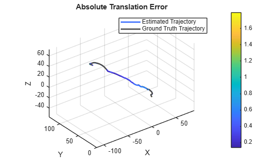
Save the LIO results so that the Validate Calibration by Building a Colorized 3-D Map Using MUN-FRL Dataset (Computer Vision Toolbox) example can colorize the map without re-running odometry.
frameIndices = allFrameIndices(1:numViews);
save lioMUNFRL.mat lioPoses lidarTimesReg frameIndices
Helper Functions
helperDownloadAndExtractMUNFRLData Download rosbag and extract sensor data.
function [lidarData, imuData, gpsData] = helperDownloadAndExtractMUNFRLData(dataFolder)
%helperDownloadAndExtractMUNFRLData Download rosbag and extract sensor data
%   Downloads the MUN-FRL lighthouse rosbag if needed, then extracts lidar
%   point clouds, IMU readings, and GPS fix data as structs.

if ~exist(dataFolder, "dir")
    mkdir(dataFolder)
end

bagFile = fullfile(dataFolder, "lighthouse_francis_sample.bag");
if ~exist(bagFile, "file")
    disp("Downloading lighthouse_francis_sample.bag (3.6 GB)...")
    url = "https://drive.usercontent.google.com/download?id=15MovyJSUhj0D2cgWNklvQTru7j6JfUwb&export=download&confirm=t";
    websave(bagFile, url, weboptions(Timeout=Inf));
end

bag = rosbag(bagFile);

% Read lidar point clouds
lidarSel = select(bag, Topic="/velodyne_points");
numLidar = height(lidarSel.MessageList);
lidarTimes = zeros(numLidar, 1);
lidarMsgs = readMessages(lidarSel, DataFormat="struct");
ptClouds = repmat(pointCloud(zeros(0,3)), numLidar, 1);
for i = 1:numLidar
    msg = lidarMsgs{i};
    lidarTimes(i) = double(msg.Header.Stamp.Sec) + double(msg.Header.Stamp.Nsec) * 1e-9;
    ptClouds(i) = pointCloud(rosReadXYZ(msg));
end
lidarData.Times = lidarTimes;
lidarData.PointClouds = ptClouds;

% Read IMU data
imuSel = select(bag, Topic="/imu/data");
imuMsgs = readMessages(imuSel, DataFormat="struct");
numIMU = numel(imuMsgs);
imuTimes = zeros(numIMU, 1);
accelData = zeros(numIMU, 3);
gyroData = zeros(numIMU, 3);
for i = 1:numIMU
    msg = imuMsgs{i};
    imuTimes(i) = double(msg.Header.Stamp.Sec) + double(msg.Header.Stamp.Nsec) * 1e-9;
    accelData(i,:) = [msg.LinearAcceleration.X, ...
        msg.LinearAcceleration.Y, ...
        msg.LinearAcceleration.Z];
    gyroData(i,:) = [msg.AngularVelocity.X, ...
        msg.AngularVelocity.Y, ...
        msg.AngularVelocity.Z];
end
imuData.Times = imuTimes;
imuData.Accel = accelData;
imuData.Gyro = gyroData;

% Read GPS fix data
fixSel = select(bag, Topic="/fix");
fixMsgs = readMessages(fixSel, DataFormat="struct");
numFix = numel(fixMsgs);
fixTimes = zeros(numFix, 1);
fixLat = zeros(numFix, 1);
fixLon = zeros(numFix, 1);
fixAlt = zeros(numFix, 1);
for i = 1:numFix
    msg = fixMsgs{i};
    fixTimes(i) = double(msg.Header.Stamp.Sec) + double(msg.Header.Stamp.Nsec) * 1e-9;
    fixLat(i) = msg.Latitude;
    fixLon(i) = msg.Longitude;
    fixAlt(i) = msg.Altitude;
end
gpsData.Times = fixTimes;
gpsData.Lat = fixLat;
gpsData.Lon = fixLon;
gpsData.Alt = fixAlt;
end
helperSyncSensorsToLidar Synchronize IMU and GPS data to lidar frame timestamps.
function [gyroSync, accelSync, gpsENU] = helperSyncSensorsToLidar(imuData, gpsData, lidarTimes)
%helperSyncSensorsToLidar Synchronize IMU and GPS data to lidar frame timestamps
%   Groups gyroscope and accelerometer readings by lidar timestamp and
%   converts GPS lat/lon/alt to local ENU interpolated at lidar times.

% Group IMU readings by lidar frame
numFrames = numel(lidarTimes);
gyroSync = cell(numFrames, 1);
accelSync = cell(numFrames, 1);
for i = 1:numFrames
    if i == 1
        mask = imuData.Times < lidarTimes(i);
    else
        mask = imuData.Times >= lidarTimes(i-1) & imuData.Times < lidarTimes(i);
    end
    gyroSync{i} = imuData.Gyro(mask,:);
    accelSync{i} = imuData.Accel(mask,:);
end

% Convert GPS lat/lon/alt to local ENU and interpolate to lidar timestamps
if exist("latlon2local", "file")
    origin = [gpsData.Lat(1), gpsData.Lon(1), gpsData.Alt(1)];
    [gpsX, gpsY, gpsZ] = latlon2local(gpsData.Lat, gpsData.Lon, gpsData.Alt, origin);
else
    gpsMatFile = load("gpsMUNFRL.mat", "gpsX", "gpsY", "gpsZ");
    gpsX = gpsMatFile.gpsX;
    gpsY = gpsMatFile.gpsY;
    gpsZ = gpsMatFile.gpsZ;
end
gpsENU = interp1(gpsData.Times, [gpsX, gpsY, gpsZ], lidarTimes);
end
helperPreprocessPointCloud Filter points by distance range and downsample for ICP.
function ptCloud = helperPreprocessPointCloud(ptCloud, distanceRange, gridStep)
%helperPreprocessPointCloud Filter points by distance range and downsample
indices = findPointsInCylinder(ptCloud, distanceRange);
ptCloud = select(ptCloud, indices);
ptCloud = pcdownsample(ptCloud, "gridAverage", gridStep);
end
References
[1] Thalagala, Ravindu G., Oscar De Silva, Awantha Jayasiri, Arthur Gubbels, George KI Mann, and Raymond G. Gosine. "MUN-FRL: A visual-inertial-LiDAR dataset for aerial autonomous navigation and mapping." The International Journal of Robotics Research 43, no. 12 (2024): 1853-1866.

