Clutter and Jammer Mitigation with STAP
This example shows how to use Simulink® to suppress clutter and jammer interference from the received pulses of a monostatic radar. It illustrates how to model clutter and jammer interference as well as how to use the adaptive displaced phase center array (ADPCA) pulse canceller block in order to suppress the interference. The ADPCA Canceller block is one of several space-time adaptive processing (STAP) blocks provided in the Phased Array System Toolbox™. For more information on modeling an end-to-end monostatic radar in Simulink® see the Simulating Test Signals for a Radar Receiver in Simulink example. For an introduction to STAP see the Introduction to Space-Time Adaptive Processing example.
Structure of the Model
This example models a monostatic radar with a moving target and a stationary barrage jammer. The jammer transmits interfering signals through free space to the radar. A six-element uniform linear antenna array (ULA) with back baffled elements then receives the reflected pulse from the target as well as the jammer's interference. A clutter simulator's output is also added to the received signal before being processed. After adding noise, the signal is buffered into a data cube. In this example the cube is processed by the ADPCA Canceller block at the target's estimated range, azimuth angle, and doppler shift. In practice the ADPCA Canceller will scan several ranges, azimuth angles and doppler shifts since the speed and position of the target is unknown.
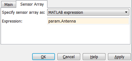
Several blocks in this example need to share the same sensor array configuration. This is done by assigning a sensor array configuration object to a MATLAB® variable and sharing this variable in the Sensor Array tab of the Block Parameter dialog box.
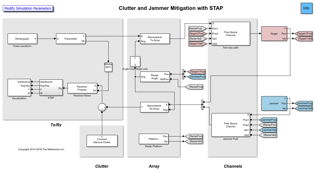
In addition to the blocks listed in the Simulating Test Signals for a Radar Receiver in Simulink example, there are:
FreeSpace -- Performs two-way propagation of the signal when you select two-way propagation is selected in the block parameters. This mode allows the use of one block instead of two to model the transmitted and reflected propagation paths of the signal.
Jammer - Generates a barrage jamming signal. This subsystem also includes a
Platformto model the speed and position of the jammer which are needed by theFreespaceblocks. The position is also needed to calculate the angle between the target and the jammer.Selector - Selects the target's angle from the
Range Angleblock. This angle is used by theNarrowband Tx Arrayblock.Constant Gamma Clutter - Generates clutter with a gamma value of -15 dB. Such a gamma value can be used to model terrain covered by woods.
Radar Platform - Updates the position and velocity of the radar.
STAP
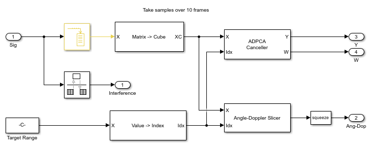
Buffer - Buffers 10 pulses of the received signal.
Matrix to Cube - Reshapes the buffered signal into an M-by-Q-by-N data cube. M is the number of range bins in fast time (the number of samples in one pulse), Q is the number of antenna elements, and N is the number of buffered pulses. The dimensions of the cube this example is 200-by-6-by-10 dimensions.
Value to Index - Calculates the index of the estimated target's range bin from the range value.
ADPCA Canceller - Perform ADPCA pulse cancelling along the specified range bin. The antenna array configuration of the radar is shared using a variable in the Sensor Array tab of the Block Parameter dialog box. The output is the received pulse with the clutter and jammer interference suppressed. The adaptive weights of the filter are also produced, enabling them is optional.
Angle Doppler Slicer - Slices the data cube along the dimension specified in the block parameters. This example examines the angle-Doppler slice of the cube at the estimated range.
Visualization - This subsystems displays the clutter interference in the time domain, the angle-Doppler response of the received data, the output of the ADPCA Canceller block, as well as the weights.
Exploring the Example
Several parameters of the model are calculated by the helper function helperslexSTAPParam. To open the function from the model, click the Modify Simulation Parameters block. This function is executed once when the model is loaded. It exports to the workspace a structure whose fields are referenced by the block parameters. To modify any parameters, either change the values in the structure at the command prompt or edit the helper function and rerun it to update the parameter structure.
Results and Displays
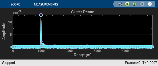
Displays from different stages of the simulation are shown here. The first figure shows how the signal received at the antenna array is dominated by the clutter return. Because the radar is located 1000 meters above the surface, the clutter returns from the ground start at 1000 meters.
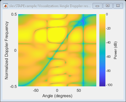
This figure shows the angle-Doppler response of the return for the estimated range bin. It presents the clutter as a function of angle and Doppler shift. The clutter return looks like a diagonal line in angle-Doppler space. Such a line is often referred to as a clutter ridge. The received jammer signal is white noise, spread over the entire Doppler spectrum at approximately 60 degrees.
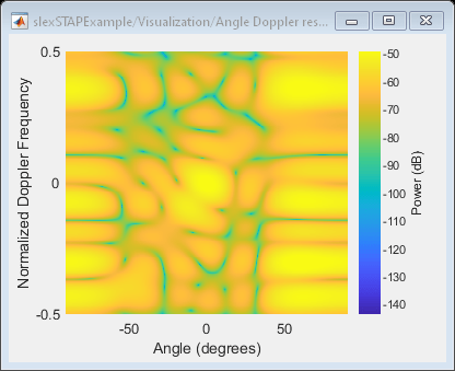
As you can see in the here, the weights of the ADPCA Canceller produce a deep null along the clutter ridge and also in the direction of the jammer.
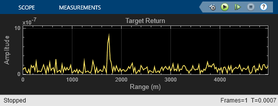
The next figure displays the return at the output of the ADPCA Canceller, clearly showing the target's range at 1750 meters. The barrage jammer and clutter have been filtered out.
