Communicate with mmWave Radar Using Connected IO
R2026bYou can use Connected IO to communicate with the IO peripherals on the hardware.
Simulation with Connected IO is an intermediate step in the Model-Based Design workflow that bridges the gap between simulation and code generation by enabling Simulink® to communicate with the hardware before deploying the model on the hardware. Connected IO enables you to modify your model design and monitor the effect of the modified design using peripheral data from the hardware in a near real-time environment. You are not required to deploy the model on the hardware to monitor the effect of the modified design, which accelerates the simulation process.
The Connected IO feature in Radar Toolbox Support Package for Texas Instruments® mmWave Radar Sensors applies to all the supported TI mmWave radar boards. In addition to the general source and sink blocks In Simulink, you can use these blocks from the Simulink library of the support package for near real-time communication using Connected IO:
Read Detections block (Source block)
With Connected IO, the Read Detections block reads data in near real-time from the TI mmWave radar board connected to your host computer.
Serial Transmit block (Sink block)
With Connected IO, the Serial Transmit block sends radar data to external interfaces in a near real-time environment. Connected IO reserves SCI module A on the TI mmWave radar for communication with the hardware. As a result, the Serial Transmit block can use only SCI module B on the TI mmWave radar.
Note
In Connected IO, only one-time deployment of IO server is required. However, if you change the configuration settings for Connected IO or change the value of non-tunable parameters in the Read Detections block, rebuild the IO server.
These sections explain:
How Connected IO Works
Connected IO creates a communication interface that enables the Simulink model and the IO Server to communicate with each other. The Simulink model resides in your computer, and the IO Server is an engine on the hardware that contains all the peripheral functions. The transport layer formats and transmits the data using the communication interface.
This diagram shows the connection that the Connected IO creates between your computer and the hardware.
Communication in Connected IO
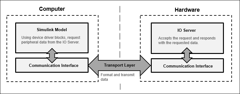
When you simulate a Simulink model with Connected IO:
During Connected IO simulations, the blocks in the model communicate with the IO Server to read data from and write data to the TI mmWave Radar and its peripherals.
The IO Server processes these communication requests by retrieving data from the hardware or applying updates to the hardware, as requested by the model. You can use Simulink sink or Dashboard blocks to monitor the received data and verify that your model behaves as expected while interacting with the hardware.
For data acquisition applications, IO Server can be pre-configured to send data at a specific rate.
For applications involving continuous data streaming, the IO Server can be preconfigured to exchange data with the hardware at a specified rate. For example, in an object tracking application, the Read Detections block streams detection data from the radar, and processes the received detections to generate object tracks.
If necessary, modify the model by adding, removing, or replacing Simulink blocks. After making changes, resimulate the model. During each simulation, the model continues to communicate with the hardware through the IO Server, enabling you to iteratively test, validate, and refine the design until the expected behavior is achieved.
Data Acquisition using Connected IO
Data acquisition can be done with Connected IO using Polling and Streaming modes.
Polling
Communication in Polling mode of Connected IO is an on-demand process. The blocks in the model request data from the IO Server, and the IO Server processes these requests by retrieving the required data from the hardware and returning it to the model. The hardware responds only when it receives a request from the Simulink model.
In this mode, you can include any number of blocks in the model as needed. It is suitable for applications that do not require real-time continuous data streaming, involve occasional reads from the hardware, or require frequent writes to the hardware.
For example, this mode can be used to read one radar frame per simulation step when triggered, or to transmit data using a Serial Transmit block.
The following image illustrates the interaction between the host and target in Polling mode.

Streaming
Streaming mode is used to achieve higher data acquisition rates for sensor and source blocks. In this mode, Simulink pre-configures the IO Server on the target to execute a specific command at the sample rate defined by the block. After configuration, the target hardware proactively transmits data at the specified rate without requiring additional requests from the model.
Because data is pushed from the hardware continuously, the response time in Streaming mode is lower compared to Polling mode, enabling high-rate data acquisition.
Only source blocks, such as Read Detections, support Streaming mode, whereas sink blocks, such as Serial Transmit operate in Polling mode.
For example, streaming is suitable when the application requires the radar to continuously transmit detection frames every 100ms, allowing Simulink to process them in real time for applications such as people tracking.
This image illustrates the interaction between the target and host computer in Streaming mode.

Connected IO in Model-Based Design
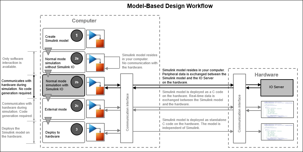
When you simulate a model without Connected IO, Simulink does not communicate with the hardware. Simulink communicates with the hardware only when the code is generated and the model is deployed on the hardware in External mode. Connected IO is an intermediate step in the model-based design workflow that bridges the gap between simulation and code generation by enabling Simulink to communicate with the hardware before deploying the model on the hardware.
This Model-Based Design Workflow diagram displays a model-based workflow:
Create a Simulink model.
Simulate the model in:
Simulation without Connected IO: There is no hardware interaction and no code generation.
Simulation with Connected IO: The model communicates with the hardware. There is no code generation.
External mode (Monitor & Tune): The model is deployed on the hardware and generates code.
Deploy the model to the hardware.
Model-Based Design Workflow
How Connected IO Differs from External Mode
Connected IO and External mode both enable you to communicate with the hardware during simulation. However, you use Connected IO and External mode for different purposes. The table shows the actions that you can perform with each mode. If your Simulink model has only Source blocks, then use Streaming mode of Connected IO to receive data in a near real-time environment.
| Action | External Mode (Monitor and Tune) | Connected IO |
|---|---|---|
| Obtain real-time data | You can obtain real-time data with External mode. | Enable the Simulation Pacing Options (Simulink) to achieve near real-time data acquisition. |
| Timing analysis of real-time data | Timing analysis of real-time data is possible because the Simulink model is running on the hardware in real-time. | Timing analysis of near real-time data is not possible because the Simulink model is running in your computer and not on the hardware. |
| Time required to start simulation | 1-2 minutes | Few seconds |
| Code generation | Code is generated on the hardware. | No code is generated. |
Run Simulink Model in Connected IO
Follow these steps to run a Simulink model in connected IO mode:
Open a Simulink model.
On the Modeling tab of the model, select Model Settings.
In the Configuration Parameters dialog box, select Hardware Implementation from the left pane and select the required TI mmWave board in the Hardware board parameter.
Under Target hardware resources, click Connected IO.
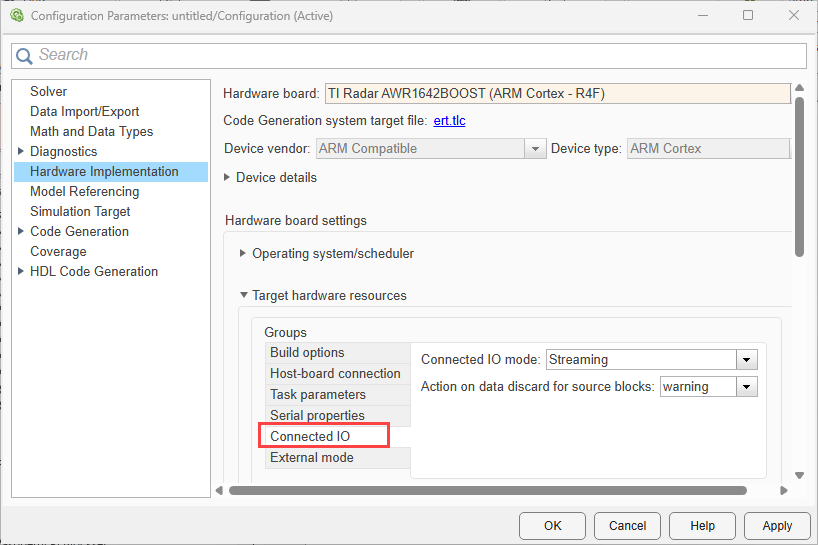
Select the required Connected IO mode (
StreamingorPolling). The default mode isStreaming.If you select
Streamingas Connected IO mode, select the required action using the Action on data discard for source blocks parameter. Data loss while streaming can occur due to the following reasons:High sample rate set for the block.
Large number of blocks in the model.
Time consuming operations in the model.

Select the required option:
warning:Select this option to display a warning when there is data loss from source blocks while streaming. After simulation, number of data dropped for each block is displayed in the diagnostic viewer.none:Select this option to take no action.error:Select this option to display an error message when there is data loss.
On the Hardware tab of the model, in the Mode section,
Connected IOis the default mode. Click Run with IO to simulate the model with Connected IO.
If your model contain sink blocks, and if you want to get near real time data, enable Simulation pacing. For more information, see Simulation Pacing Options (Simulink).


