Design Superheterodyne Receiver Using Analog Device Components
R2026bThis example shows how to analyze the RF budget of a dual-conversion superheterodyne receiver built from Analog Devices® amplifiers and mixers in the RF Parts Catalog. The example uses the intermodulation table (IMT) mixer model, which characterizes mixer behavior from measured data at the operating frequencies.
The receiver design and part selection follow directly from the receiver architecture, so the next section defines that architecture before you pick the parts.
Receiver Architecture
A superheterodyne receiver translates an incoming RF signal to a lower intermediate frequency (IF). Splitting the total 10 GHz-to-100 MHz translation into two mixing stages keeps each stage's LO-to-IF frequency ratio , which optimizes the filter selectivity required to reject image and spurious products.
In this example, the receiver downconverts a 10 GHz RF input to a 100 MHz output through the following parts connected in cascade:
RF Input (10 GHz) -> LNA -> 1st Mixer -> IF Amp -> 2nd Mixer -> Output
The low-noise amplifier (LNA) sets the receiver noise floor. The first mixer performs the frequency translation, and the IF amplifier restores level between mixers. The second mixer places the signal at the final IF for baseband processing.
The frequency plan uses high-side local oscillator (LO) injection at each stage (LO above RF), which produces a lower-sideband IF and places the image frequency far above the input band where preselection or LNA rolloff attenuates it:
1st Stage: RF = 10 GHz, LO = 12.5 GHz, IF1 = 2.5 GHz (HMC8191LC4)
2nd Stage: IF1 = 2.5 GHz, LO = 2.6 GHz, IF2 = 100 MHz (HMC8193LC4)
For a complete receiver chain that adds filters and interconnects and uses the nonlinear mixer model, see Design Superheterodyne Receiver with Nonlinear Mixers.
Select Low-Noise Amplifier for RF Front End
The first stage sets the system noise figure, so choose an amplifier with high gain and low noise figure across the RF band. The HMC902LP3E covers 5-10 GHz with 19.9 dB gain and 2.0 dB noise figure at 10 GHz.
warning off;
installRFParts()
lnaSelector = rfPartSelector("Type", "amplifier");
add(lnaSelector,"SelectedSearchParameters", "RFPrimaryFunction", "LNA",...
    "InputFrequency", 10e9, "NoiseFigureRange", [0 2.5], "GainRange", [15 30]);
show(lnaSelector, 'selected')
lna = rfPart(lnaSelector, "HMC902LP3E");
fprintf("LNA: %s (Gain=%.1f dB, NF=%.1f dB @ %.0f GHz)\n", ...
    lna.Name, lna.Gain, lna.NF, lna.InputFrequency/1e9);
    List_No     Part Number            RF Primary Function           Min Freq (MHz)    Max Freq (MHz)    Gain (dB) @ 10000 MHz    Noise Figure (dB) @ 10000 MHz    OP1dB (dBm) @ 10000 MHz    OIP3 (dBm) @ 10000 MHz    OPSAT (dBm) @ 10000 MHz    Voltage (V)    Current (mA)    Operating Temp (degC)     Package Type
    _______    ______________    ________________________________    ______________    ______________    _____________________    _____________________________    _______________________    ______________________    _______________________    ___________    ____________    _____________________    _______________

       1       "ADL8105"         "Driver Amp Gain Block LNA"               4000            22000                28.396                        1.748                        18.777                     29.913                    20.478                   5             90                  25              "8-lead LFCSP"
       2       "ADL9006ACGZN"    "LNA Wideband Distributed Amps"           2000            28000                15.482                         1.75                         18.94                      24.49                     19.44                   5             53                  25              "32-Lead LFCSP"
       3       "ADL9006_Die"     "LNA Wideband Distributed Amps"         2009.5            28010                15.249                       1.5996                        19.061                     24.307                    20.061                   5             55                  25              "CHIPS OR DIE"
       4       "HMC516_Die"      "LNA"                                     6000            18000                20.338                          2.1                            15                       24.5                        17                   3             65                  25              "CHIPS OR DIE"
       5       "HMC564LC4"       "LNA Low Phase Noise"                     7000            14000                18.387                          1.9                            13                     25.867                        15                   3             51                  25              "24-Lead LCC"
       6       "HMC564_Die"      "LNA Low Phase Noise"                     7000            13500                17.952                       1.8333                          12.5                     23.967                      14.5                   3             51                  25              "CHIPS OR DIE"
       7       "HMC565LC5"       "LNA"                                     6000            20000                23.638                          2.5                           9.3                       20.1                      11.3                   3             53                  25              "32-Lead LCC"
       8       "HMC565_Die"      "LNA"                                     6000            20000                22.944                          2.2                           9.3                       20.5                      11.3                   3             53                  25              "CHIPS OR DIE"
       9       "HMC772"          "LNA"                                     2000            12000                16.017                            2                          12.3                       25.3                      14.3                   4             45                  25              "24-Lead LCC"
      10       "HMC8410_Die"     "Gain Block LNA Low Phase Noise"          1100            10000                 15.11                         1.64                         19.31                      30.57                     22.24                   5             65                  25              "CHIPS OR DIE"
      11       "HMC902LP3E"      "LNA"                                     5000            10000                 19.88                            2                          15.6                       27.6                      17.6                 3.5             80                  25              "16-Lead LFCSP"
      12       "HMC902_Die"      "LNA"                                     5000            10000                21.241                          1.7                          16.9                       28.4                      18.9                 3.5             80                  25              "Die"
      13       "HMC903LP3E"      "LNA"                                     6000            17000                17.389                          1.6                          14.2                     25.533                      16.2                 3.5             80                  25              "16-Lead LFCSP"
      14       "HMC903_Die"      "LNA"                                     6000            18000                19.404                          1.4                          16.1                       27.8                      18.1                 3.5             90                  25              "Die"

LNA: HMC902LP3E (Gain=20.6 dB, NF=1.6 dB @ 8 GHz)
Downconvert RF Signal to First IF with Wideband IQ Mixer
To translate the 10 GHz input to a 2.5 GHz first IF, use the HMC8191LC4 in-phase/quadrature (IQ) mixer with a 12.5 GHz local oscillator. Filter the IMT-modeled parts by selecting the DownConverter converter type. The mixer takes the lower-sideband product LO - RF.
mixer1Selector = rfPartSelector("Type", "mixer");
Use the add function to add the search parameters to refine your component selection.
add(mixer1Selector,"SelectedSearchParameters", ...
    "ModelType", "IMT", ...
    "ConverterType", "DownConverter","Sideband","LSB", ...
    "InputFrequency", 10e9, "LOFrequency", 12.5e9);
remove(mixer1Selector, 'DisplayColumns', {'Package Type','Operating Temp (degC)'});
add(mixer1Selector, 'DisplayColumns', {'Converter Type','Model Type','Sideband','Gain (dB)'});
show(mixer1Selector,'selected')
    List_No    Part Number       RF Primary Function      Converter Type     Model Type    Sideband    Min RF Freq (MHz)    Max RF Freq (MHz)    Min IF Freq (MHz)    Max IF Freq (MHz)    Min LO Freq (MHz)    Max LO Freq (MHz)    Gain (dB) @ 10000 MHz
    _______    ____________    _______________________    _______________    __________    ________    _________________    _________________    _________________    _________________    _________________    _________________    _____________________

       1       "ADMV1530"      "Double Sideband Mixer"    "DownConverter"      "IMT"        "LSB"            3000                 23000                1000                 10000                8000                 24000                 -10.396
       2       "HMC8191LC4"    "IQ Mixer"                 "DownConverter"      "IMT"        "LSB"            5000                 27000                 100                  5000                6100                 31000                 -9.3548
Use the rfpart function to create a mixerIMT object from lower-sideband HMC8191LC4 mixer.
mixer1 = rfPart(mixer1Selector, "HMC8191LC4");
fprintf("1st Mixer: %s (RF=%.1f GHz, LO=%.1f GHz, IF=%.1f GHz)\n", ...
    mixer1.Name, mixer1.InputFrequency/1e9, mixer1.LO/1e9, ...
    abs(mixer1.LO - mixer1.InputFrequency)/1e9);
1st Mixer: HMC8191LC4 (RF=15.0 GHz, LO=15.1 GHz, IF=0.1 GHz)
Amplify First IF Signal Before Second Downconversion
The first mixer has conversion loss, so restore signal level and preserve the dynamic range budget with an IF amplifier. The ADL5521_5V covers 850-3600 MHz with 13.4 dB gain and 0.9 dB noise figure at 2.5 GHz.
ifAmpSelector = rfPartSelector("Type", "amplifier");
add(ifAmpSelector, 'SelectedSearchParameters', ...
    'InputFrequency', 2.5e9, 'OIP3Range', [30 50], 'OP1dBRange', [18 30]);
ifAmp = rfPart(ifAmpSelector, "ADL5521_5V");
fprintf("IF Amp: %s (Gain=%.1f dB, NF=%.1f dB @ %.1f GHz)\n", ...
    ifAmp.Name, ifAmp.Gain, ifAmp.NF, ifAmp.InputFrequency/1e9);
IF Amp: ADL5521_5V (Gain=21.0 dB, NF=0.9 dB @ 0.8 GHz)
Downconvert to Final 100 MHz IF Output
The second stage translates the 2.5 GHz first IF to a 100 MHz output suitable for baseband processing. Use the HMC8193LC4 IQ mixer with a 2.6 GHz local oscillator to take the LO - IF1 product.
mixer2Selector = rfPartSelector("Type", "mixer");
mixer2Selector.add("SelectedSearchParameters", ...
    "ModelType", "IMT", ...
    "ConverterType", "DownConverter");
mixer2 = rfPart(mixer2Selector, "HMC8193LC4");
mixer2.InputFrequency = 2.5e9;
mixer2.LO = 2.6e9;
fprintf("2nd Mixer: %s (RF=%.1f GHz, LO=%.1f GHz, IF=%.0f MHz)\n", ...
    mixer2.Name, mixer2.InputFrequency/1e9, mixer2.LO/1e9, ...
    abs(mixer2.LO - mixer2.InputFrequency)/1e6);
2nd Mixer: HMC8193LC4 (RF=2.5 GHz, LO=2.6 GHz, IF=100 MHz)
Assemble Receiver Cascade for RF Budget Analysis
Combine the four Analog Devices parts into a cascade and pass them to the rfbudget object with the RF input conditions. Use a -30 dBm input power to keep all stages in their linear region and a 20 MHz bandwidth typical of a wideband communication channel.
rfFreq = 10e9;       % RF input frequency
inputPower = -30;    % Available input power (dBm)
bw = 20e6;           % Signal bandwidth
rxBudget = rfbudget([lna, mixer1, ifAmp, mixer2], rfFreq, inputPower, bw);
Report Stage-by-Stage and System-Level Performance
Inspect gain, noise figure, and third-order intercept at each stage to verify that the receiver meets the design goals. The final-row values summarize end-to-end system performance.
fprintf("\n=== Superheterodyne Receiver RF Budget ===\n");
fprintf("%-15s %-12s %-12s %-12s %-12s %-12s\n", ...
    "Stage", "Freq(GHz)", "Gain(dB)", "NF(dB)", "IIP3(dBm)", "OIP3(dBm)");
fprintf("%s\n", repmat('-', 1, 75));

stageNames = {lna.Name, mixer1.Name, ifAmp.Name, mixer2.Name};
for k = 1:numel(stageNames)
    fprintf("%-15s %-12.3f %-12.2f %-12.2f %-12.2f %-12.2f\n", ...
        stageNames{k}, ...
        rxBudget.OutputFrequency(k)/1e9, ...
        rxBudget.TransducerGain(k), ...
        rxBudget.NF(k), ...
        rxBudget.IIP3(k), ...
        rxBudget.OIP3(k));
end

fprintf("\n=== System Performance Summary ===\n");
fprintf("RF Input:            %.2f GHz\n", rfFreq/1e9);
fprintf("1st IF:              %.2f GHz\n", 2.5);
fprintf("2nd IF (output):     %.0f MHz\n", 100);
fprintf("Signal Bandwidth:    %.0f MHz\n", bw/1e6);
fprintf("Input Power:         %.0f dBm\n", inputPower);
fprintf("Output Power:        %.2f dBm\n", rxBudget.OutputPower(end));
fprintf("System Gain:         %.2f dB\n", rxBudget.TransducerGain(end));
fprintf("System NF:           %.2f dB\n", rxBudget.NF(end));
fprintf("System IIP3:         %.2f dBm\n", rxBudget.IIP3(end));
=== Superheterodyne Receiver RF Budget ===
Stage           Freq(GHz)    Gain(dB)     NF(dB)       IIP3(dBm)    OIP3(dBm)
---------------------------------------------------------------------------
HMC902LP3E      10.000       19.88        2.00         7.69         27.60
HMC8191LC4      5.100        9.08         2.00         7.69         16.80
ADL5521_5V      5.100        18.58        2.10         7.29         25.90
HMC8193LC4      2.500        11.38        2.10         7.29         18.70

=== System Performance Summary ===
RF Input:            10.00 GHz
1st IF:              2.50 GHz
2nd IF (output):     100 MHz
Signal Bandwidth:    20 MHz
Input Power:         -30 dBm
Output Power:        -18.62 dBm
System Gain:         11.38 dB
System NF:           2.10 dB
System IIP3:         7.29 dBm
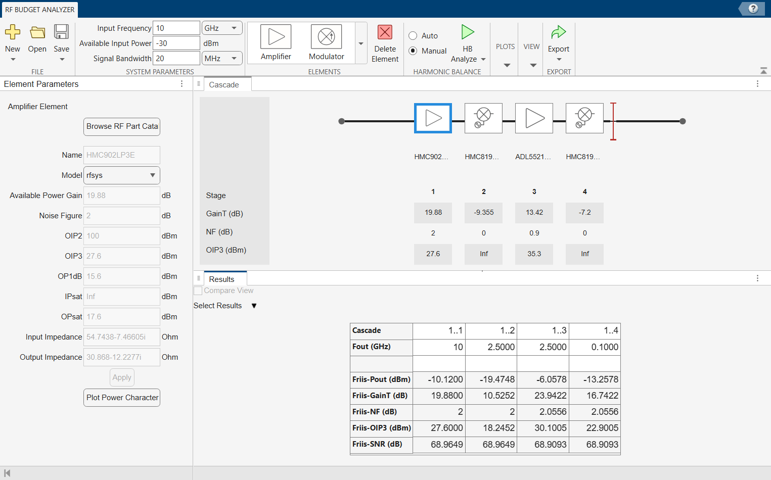
Explore Chain Interactively in RF Budget Analyzer App
Open the RF Budget Analyzer app to visualize gain, noise figure, and other parameters across the chain.
show(rxBudget)
See Also
Superheterodyne Receiver Using RF Budget Analyzer App | Design Superheterodyne Receiver with Nonlinear Mixers

