Extract S-Parameters from Circuit
This example uses the Symbolic Math Toolbox™ to explain how the RF Toolbox™ extracts two-port S-parameters from an RF Toolbox circuit object.
Consider a two-port network as shown in the figure 1 that you want to characterize with S-parameters. The formal S-parameters definition using power waves can be rewritten as in the case of a real scalar reference impedance .
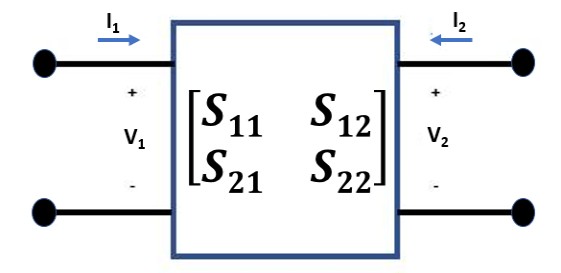
Figure 1: Two-Port Network
To extract the S-parameters from a circuit into an sparameters object, the RF Toolbox terminates each port with the reference impedance . Then, the RF Toolbox independently drives each port j, with a current equal to and solves for the port voltages . Driving with current sources is the Norton equivalent of driving with a 1-volt voltage source and a series resistance of .
Measure the port voltage at node i when node j is driven.
If i j, the S-parameter entry is simply twice the port voltage , and this is given using the equation .
The diagonal entries of S-parameters when are given using the equation .
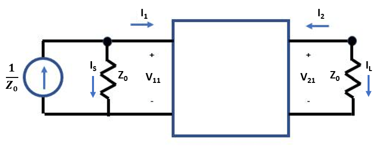
Figure 2: Circuit Driven at Port 1 with Current Source
Write Constitutive and Conservative Equations of Circuit
Circuits are represented in node-branch form in the RF Toolbox. There are four branches in the circuit represented in figure 2, one for the input port, two for the two-port nport object, and one for the output port. This means that the circuit has four branch current unknowns , , , and and two node voltages and . To represent the circuit described in figure 2 in node-branch form, you need four constitutive equations to represent the branch currents and two conservative equations to represent the node voltages.
syms F IS I1 I2 IL V1 V2 Z0
syms S11 S12 S21 S22

nI = 4; % number of branch currents
nV = 2; % number of node voltages

% F = [Fconstitutive; Fconservative]
F = [
    V1 - Z0*IS
    V1 - Z0*I1 - S11*(V1+Z0*I1) - S12*(V2+Z0*I2)
    V2 - Z0*I2 - S21*(V1+Z0*I1) - S22*(V2+Z0*I2)
    V2 - Z0*IL
    IS+I1
    I2+IL
    ]
F =
Jacobian Evaluation of Circuit
Use the jacobian function from the Symbolic Math Toolbox to compute the matrix of derivatives of the function F with respect to the six unknowns (four branch currents and two node voltages).
J = jacobian(F,[IS; I1; I2; IL; V1; V2])
J =
Solve S-Parameters of Circuit
Create a two-column right-hand side vector, rhs, to represent the driving of each port.
syms rhs [nI+nV 2]
syms x v S

% Compute S-parameters of cascade
rhs(:,:) = 0;
rhs(nI+1,1) = 1/Z0;  % rhs for driving input port
rhs(nI+nV,2) = 1/Z0  % rhs for driving output port
rhs =
To solve for the voltages, back solve the rhs with the Jacobian. The S-parameter matrix that MATLAB® outputs represents the two-port circuit shown in figure 1.
x = J \ rhs;
v = x(nI+[1 nV],:);
S = 2*v - eye(2)
S =