Main Content

interdigitalCapacitor

Create basic interdigital capacitor

Since R2021b

Description

Use the interdigitalCapacitor object to create an interdigital planar capacitor (IDC). IDCs are used in high frequency applications such as:

  • Receiver circuits where antenna radiators are connected to RF

  • Wireless data communications with RFID

  • Humidity and solution concentration measurements

  • Lab-on-chip devices (LOCs)

Note

This PCB object supports behavioral modeling. For more information, see Behavioral Models. To analyze the behavioral model for a interdigital capacitor, set the Behavioral property in the sparameters function to true or 1

Three part image from right to left: Default image of a interdigital capacitor. Current distribution on the interdigital capacitor. S-parameters plot of the interdigital capacitor.

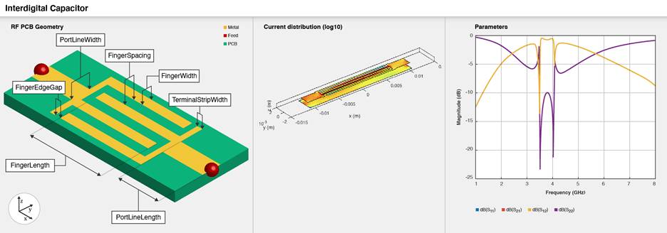
A two-port series IDC with microstrip form feeder lines supports single and multiple dielectrics. It is a coplanar structure consisting of multiple comb electrodes or intersecting fingers with spaces between the fingers. An IDC can have identical port line lengths and widths on either sides.

Creation

Description

example

capacitor = interdigitalCapacitor creates a basic interdigital capacitor with default property values for an operating bandwidth of 3.6-4 GHz.

example

capacitor = interdigitalCapacitor(Name=Value) sets Properties using one or more name-value arguments. For example, interdigitalCapacitor(NumFingers=10) creates an interdigital capacitor with 10 fingers. Properties not specified retain their default values.

Properties

expand all

Number of fingers on the capacitor, specified as a positive scalar.

Example: capacitor = interdigitalCapacitor(NumFingers=10)

Data Types: double

Length of the overlapping fingers in meters, specified as a positive scalar.

Example: capacitor = interdigitalCapacitor(FingerLength=0.0217)

Data Types: double

Width of the overlapping fingers in meters, specified as a positive scalar.

Example: capacitor = interdigitalCapacitor(FingerWidth=4.8000e-04)

Data Types: double

Distance between the fingers in meters, specified as a positive scalar.

Example: capacitor = interdigitalCapacitor(FingerSpacing=2.9000e-04)

Data Types: double

Gap between the edges of the fingers in meters, specified as a positive scalar.

Example: capacitor = interdigitalCapacitor(FingerEdgeGap=2.05000e-04)

Data Types: double

Width of the terminals in meters, specified as a positive scalar.

Example: capacitor = interdigitalCapacitor(TerminalStripWidth=4.9000e-04)

Data Types: double

Width of the ports in meters, specified as a positive scalar.

Example: capacitor = interdigitalCapacitor(PortLineWidth=0.0020)

Data Types: double

Length of the ports in meters, specified as a positive scalar.

Example: capacitor = interdigitalCapacitor(PortLineLength=0.0040)

Data Types: double

Height from the capacitor to the ground plane in meters, specified as a positive scalar.

Example: capacitor = interdigitalCapacitor(Height=6.9000e-04)

Data Types: double

Width of the ground plane in meters, specified as a positive scalar.

Example: capacitor = interdigitalCapacitor(GroundPlaneWidth=0.0040)

Example: double

Type of dielectric material used as a substrate, specified as a dielectric object. The dielectric material in a interdigitalCapacitor with default properties have the following properties:

  • Name{'Roger'}

  • EpsilonR3.2

  • LossTangent0.0002

  • Thickness0.000787

Example: d = dielectric("FR4"); capacitor = interdigitalCapacitor(Substrate=d)

Data Types: string | char

Type of metal used in the conducting layers, specified as a metal object. he type of metal in a couplerBranchlineWideband object with default properties is Copper.

Example: m = metal("PEC"); capacitor =interdigitalCapacitor(Conductor=m)

Data Types: string | char

Flag to add a metal shielding to the PCB component, specified as a logical 0 or logical 1. The default value is logical 0.

Example: IsShielded = true or 1 add a metal shield.

Note

To enable FEM solver required for the metal shield property, download the Integro-Differential Modeling Framework for MATLAB. To download this add-on:

  1. In the Home tab Environment section, click on Add-Ons. This opens the add-on explorer. You need an active internet connection to download the add-on.

  2. Search for Integro-Differential Modeling Framework for MATLAB and click Install.

  3. To verify if the download is successful, run

    matlab.addons.installedAddons
    in your MATLAB® session command line.

  4. On Windows, to run the IDMF add-on, you must install the Windows Subsystem for Linux (WSL). To install WSL, see Install Linux on Windows with WSL.

    The Windows Defender Firewall can block the PostgreSQL server when using the IDMF add-on. To resolve this issue, you can allow the server to communicate on desired networks if the firewall prompts. Alternatively, you can manually add the executable file of the PostgreSQL server located in <matlabroot>\sys\postgresql\win64\PostgreSQL\bin\postgres.exe. For more information regarding firewalls, see Allowing apps through Windows Defender Firewall .

Data Types: logical

This property is read-only.

Metal shield for the PCB component, specified as a shape.Box object. The length and width of the box must be equal to the length and width of the ground plane. The center of the box is at [0 0 Shielding.Height]. You can modify the property after creating the object.

Dependencies

To enable the Shielding property, set the IsShielded property to true or 1.

Type of RF connector assembled at the feed locations of the PCB component, specified as a RFConnector object.

Example: Create connector from RFConnector object like this: coaxial = RFConnector adds a coaxial connector.

Dependencies

To enable the Connector property, set the IsShielded property to true or 1.

Object Functions

capacitanceCalculate capacitance
chargeCalculate and plot charge distribution
currentCalculate and plot current distribution
feedCurrentCalculate current at feed port
getZ0Calculate characteristic impedance of transmission line
layoutPlot all metal layers and board shape
meshChange and view mesh properties of metal or dielectric in PCB component
shapesExtract all metal layer shapes of PCB component
showDisplay PCB component structure or PCB shape
sparametersCalculate S-parameters for RF PCB objects
RFConnectorCreate RF connector

Examples

collapse all

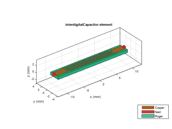
Create and view a default interdigital capacitor.

idcapacitor = interdigitalCapacitor
idcapacitor = 
  interdigitalCapacitor with properties:

            NumFingers: 4
          FingerLength: 0.0137
           FingerWidth: 3.1600e-04
         FingerSpacing: 3.0000e-04
         FingerEdgeGap: 3.4100e-04
    TerminalStripWidth: 5.0000e-04
         PortLineWidth: 0.0019
        PortLineLength: 0.0030
                Height: 7.8700e-04
      GroundPlaneWidth: 0.0030
             Substrate: [1x1 dielectric]
             Conductor: [1x1 metal]
            IsShielded: 0

show(idcapacitor)

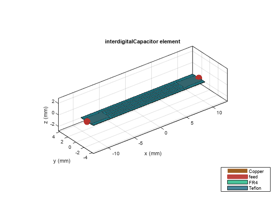
Create and view a multilayer interdigital capacitor with two different dielectrics.

idcapacitor = interdigitalCapacitor;
sub = dielectric("FR4","Teflon"); 
sub.Thickness =[0.00003 0.00003];
idcapacitor.Substrate = sub;
idcapacitor.Height = 0.00003;
show(idcapacitor);

Create an interdigital capacitor using gold as the conductor.

capacitor = interdigitalCapacitor;
capacitor.Conductor = metal("Gold");
show(capacitor)

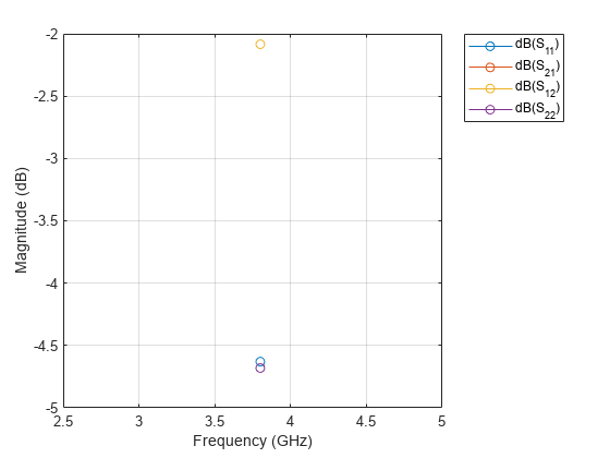
Compute and plot the behavioral S-parameters of the capacitor at 3.8 GHz.

spar = sparameters(capacitor,3.8e9,Behavioral=true);
rfplot(spar)

More About

expand all

References

[1] Pozar, David M. Microwave Engineering. 4th ed. Hoboken, NJ: Wiley, 2012.

[2] Jungreuthmayer, Christian, Gerald M. Birnbaumer, Peter Ertl, and Jürgen Zanghellini. “Improving the Measurement Sensitivity of Interdigital Dielectric Capacitors (IDC) by Optimizing the Dielectric Property of the Homogeneous Passivation Layer.” Sensors and Actuators B: Chemical 162, no. 1 (February 2012): 418–24. https://doi.org/10.1016/j.snb.2011.12.009.

[3] Ruppin, R. “Surface Polaritons of a Left-Handed Material Slab.” Journal of Physics: Condensed Matter 13, no. 9 (March 5, 2001): 1811–18. https://doi.org/10.1088/0953-8984/13/9/304.

[4] Caloz, Christophe, and Tatsuo Itoh. Electromagnetic Metamaterials: Transmission Line Theory and Microwave Applications: The Engineering Approach. Hoboken, NJ, USA: John Wiley & Sons, Inc., 2005. https://doi.org/10.1002/0471754323.

Version History

Introduced in R2021b

expand all