Simulate Automated Parking Valet with ROS 2 in Simulink
This example shows how to distribute components of the Automated Parking Valet application into various Simulink® models and simulate them in a known parking lot environment.
Explore Simulink ROS 2 Nodes and Connectivity
Observe the division of the components into four separate Simulink models. Each Simulink model represents a ROS 2 node.
Vehicle Node
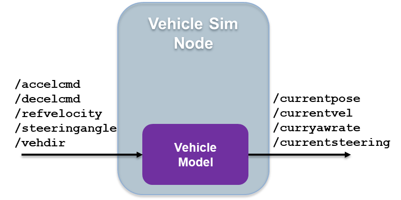
1. Open the vehicle model.
open_system('ROS2ValetVehicleExample'); 2. To simulate the vehicle controller effects and output the vehicle information, the Vehicle model subsystem uses a Bicycle Model (Automated Driving Toolbox) block and a Vehicle Body 3DOF block.
Behavioral Planner Node

1. Open the behavioral planner model.
open_system('ROS2ValetBehavioralPlannerExample'); 2. This model reads the current vehicle information, sends the next goal and checks if the vehicle has reached the final pose of the segment using rosAutomatedValetHelperGoalChecker.
3. The Behavioral Planner and Goal Checker subsystem runs when a new message is available on either /currentvel or /currentpose.
4. The model sends the status if the vehicle has reached the final parking goal using the /reachgoal topic, which uses a std_msgs/Bool message type. All the models stop simulation when this message is true.
Path Planner Node
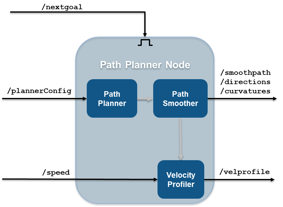
1. Open the path planner model.
open_system('ROS2ValetPathPlannerExample'); 2. This model plans a feasible path through the environment map using a pathPlannerRRT (Automated Driving Toolbox) object, which implements the optimal rapidly exploring random tree (RRT*) algorithm and sends the plan to the controller.
3. The Path Planner subsystem runs when a new message is available on /plannerConfig or /nextgoal topics.
Controller Node
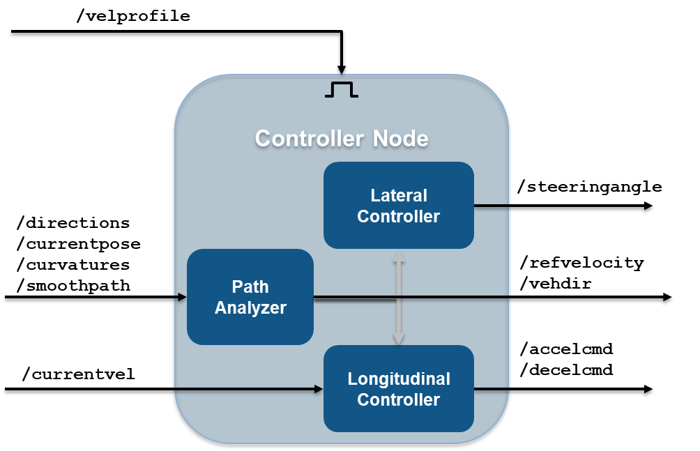
1. Open the vehicle controller model.
open_system('ROS2ValetControllerExample');2. This model calculates and sends the steering and velocity commands.
3. The Controller subsystem runs when a new message is available on the /velprofile topic.
Simulate ROS 2 Nodes to Verify Partitioning
Model references in this example use Variant Subsystem (Simulink) to achieve easy switch between simulation and code generation. During simulation, messages pass from one node to other directly without ROS 2 blocks to showcase the data flow and execution order among these four ROS 2 nodes. During code generation, variant subsystem under each node will use publish and subscribe blocks to replace input and output ports. In this way, after we lock down the control algorithm during simulation, each node can be deployed as a standalone ROS 2 node without any changes to the model.
Verify that the behavior of the model remains the same after partitioning the system into four Simulink models.
1. Load the pre-recorded localization map data in MATLAB® base workspace using the exampleHelperROSValetLoadLocalizationData helper function.
exampleHelperROSValetLoadLocalizationData;
2. Open the simulation model.
open_system('ROS2ValetSimulationExample.slx');In the left parking selection area, you can also select a spot. The default parking spot is the sixth spot at the top row.
3. In the Simulation tab, click Run from SIMULATE section or run sim('ROS2ValetSimulationExample.slx') in MATLAB Command Window. A figure opens and shows how the vehicle tracks the reference path. The blue line represents the reference path while the red line is the actual path traveled by the vehicle. Simulation for all the models stop when the vehicle reaches the final parking spot.
sim('ROS2ValetSimulationExample.slx');
Simulation Results
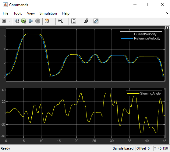
The Visualization subsystem in vehicle model generates the results for this example.
open_system('ROS2ValetVehicleExample/Vehicle model/Visualization');The visualizePath block is responsible for creating and updating the plot of the vehicle paths shown previously. The vehicle speed and steering commands are displayed in a scope.
open_system("ROS2ValetVehicleExample/Vehicle model/Visualization/Commands")