Simulink Function Blocks and Code Generation
Why Generate Code from Simulink Function Blocks and Function Callers?
Simulink Function blocks provide a mechanism for generating C or C++ code for modeling components that represent shared resources. You define the logic as a resource in a Simulink Function block, which separates the function interface (name and arguments) from the implementation of the logic. Function callers (Function Caller blocks, MATLAB Function blocks, and Stateflow® charts) can then reuse the function logic at different levels of the model hierarchy.
Simulink Function blocks provide an alternative to reusable subsystems. For example, a consideration for using a Simulink Function block instead of a subsystem block is that a Simulink Function block shares states between function callers. The code generator produces one function. If the Simulink Function block contains blocks that have states, such as a delay or memory, the states persist between function callers. The order of the function calls is an important consideration.
Reusable functions that the code generator produces from subsystems do not share states. The code generator produces one function for multiple instances of the subsystem as an optimization. If that subsystem contains blocks that have states, the code generator produces one function, but passes a different state variable to each instance. The instances do not share states.
Other uses of Simulink Function blocks and callers include:
Nesting calls to a function.
Calling a function defined in one modeling component from another modeling component.
Generating functions that are globally accessible or scoped.
Generating functions that reuse arguments as input and output.
Customizing function interfaces in the generated code for subsystems or Stateflow charts.
Customizing interfaces of export functions in the generated code.
Producing code for a client and server application.
Implementation Options
Choose how to implement Simulink® functions and function callers based on your code generation requirements. Considerations include:
How you represent a function and function callers in a model
Scope of a function
Whether to export a function from a model (requires Embedded Coder®)
Function code interface customizations (requires Embedded Coder)
Code generation requirements
Code generation limitations
Choose a Modeling Pattern
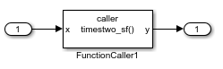
This table shows C code for a function that multiplies an input value times two and a Simulink Function block that can represent that function in a Simulink model.
| Function Definition | Modeling Element |
|---|---|
#include "timestwo_sf.h"

#include "ex_slfunc_comp_sf.h"
#include "ex_slfunc_comp_sf_private.h"

void timestwo_sf(real_T rtu_x, real_T *rty_y)
{
  *rty_y = 2.0 * rtu_x;
} | Simulink Function block
|

A Simulink function caller invokes a function defined with a Simulink Function block. From anywhere in a model or chart hierarchy, you can call a function defined with a Simulink Function block by using one of these modeling elements:
| Function Call | Modeling Element |
|---|---|
void ex_slfunc_comp_sf_step(void)
{
  real_T rtb_FunctionCaller1;

timestwo_sf(ex_slfunc_comp_sf_U.In1, &rtb_FunctionCaller1);

ex_slfunc_comp_sf_Y.Out1 = rtb_FunctionCaller1;
.
.
. | Function Caller block
|
void ex_slfunc_comp_gf_step(void)
{
  real_T rtb_y1_l;

  timestwo_gf(ex_slfunc_comp_gf_U.In4, &rtb_y1_l);

  ex_slfunc_comp_gf_Y.Out4 = rtb_y1_l;
  .
  .
. | Stateflow chart transition
|
void ex_slfunc_comp_mf_step(void)
{
  real_T rtb_y;

  timestwo_mf(ex_slfunc_comp_mf_U.In3, &rtb_y);

  ex_slfunc_comp_mf_Y.Out3 = rtb_y;
  .
  .
. | MATLAB Function block
|


For more information about modeling choices, see Simulink Functions Overview.
Specify Function Scope
A function that you define with a Simulink Function block can be global or scoped.
Global - The code generator places code for a global function in source and header files that are separate from model code files (for example,
function.cfunction.hScoped - The code generator places code for a scoped function in model code files (
model.cmodel.hTo create a library of functions that are accessible from anywhere in the generated model code, set up each function as a scoped Simulink Function block. Place each scoped function within a virtual subsystem at the root level of a model.
For more information, see and Scoped, Global, and Port-Scoped Simulink Function Blocks Overview.
Decide Whether to Generate Export Function Code
Although you can use Simulink Function blocks in a single top-model design, function code is more reusable when you generate it as standalone, atomic components. If you are using Embedded Coder, you can design functions in the context of export-function models.
For information, see Generate Component Source Code for Export to External Code Base (Embedded Coder) and Export-Function Models Overview.
Configure Function Code Interfaces
With Embedded Coder, simplify integration of generated code with external code by configuring generated function code interfaces for Simulink Function and Function Caller blocks. You can configure the function interfaces for:
Global Simulink Function blocks
Scoped Simulink Function blocks that are at the root level of a model
For more information, see Configure C Entry-Point Function Interfaces for Simulink Function and Function Caller Blocks (Embedded Coder).
Uncalled Simulink Function Blocks
If you use a Simulink Function block in a rate-based model and do not call that function, the code generator treats the Simulink Function block as a constant and does not produce function code. For example, this can occur during model development when you are ready to define a function, but are not ready to identify a caller.
To identify such blocks in a rate-based model, display sample time colors during simulation (see View Sample Time Information). By default, Constant blocks appear magenta. Because the code generator considers uncalled Simulink Function blocks constants during simulation, they appear magenta.
Requirements
Within a model hierarchy, function names are unique. If the code generator finds multiple functions with the same name, it issues an error. Change the name of one of the functions and delete the
slprjfolder.The signature (for example, the arguments and argument data types) for a function and function callers must match.
If the code generator finds the function first and the signature of a function caller does not match, the code generator issues an error. Change the function caller signature to match the signature of the Simulink Function block or delete the
slprjfolder.If the code generator finds a function caller first and the signature of the function does not match, the code generator issues a warning message. Change the signature of the function or function caller so that the signatures match.
In a Simulink Function block definition, do not define input and output signals for Argument Inport and Argument Outport blocks with a storage class.
Do not specify Argument Inport and Argument Outport blocks as test points.
If you specify the data type of input and output signals for Argument Inport and Argument Outport blocks as a
Simulink.IntEnumType,Simulink.AliasType, orSimulink.Bus, set theDataScopeproperty toImportedorExported.A function interface and function callers must agree in data type, complexity, dimension, and number of arguments.
Limitations
Simulink functions and function callers do not honor the
MaxStackSizeparameter.To generate code for a model that uses the Function Caller block to call and execute a Simulink or exported Stateflow function asynchronously, you must set model configuration parameter System target file to
autosar_adapative.tlc. For other system target file settings, clear Function Caller block parameter Execute function call asynchronously.
Generate Code for Simulink Function and Function Caller
This example shows how to generate C code for Simulink Function and Function Caller blocks and displays the relevant generated code.
Open the example model SimulinkFunctionsTestHarness. The model uses Stateflow software, but this example reviews only the code generated from the referenced models.
open_system('SimulinkFunctionsTestHarness')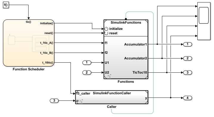
Generate Code for Function Definition
Open model SimulinkFunctions. The Simulink Function block is the f3 subsystem defined as y = f3(u).
open_system('SimulinkFunctions')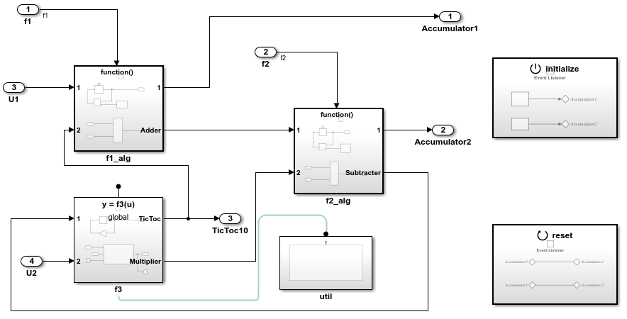
Generate code. The code generator creates SimulinkFunctions.c. This file contains the function initialization code and function definition.
Initialization code for function f3:
void SimulinkFunctions_initialize(void)
{
  rtDWork.Delay_DSTATE = 1;
}
Code for function f3:
void f3(real_T rtu_u, real_T *rty_y)
{
  int8_T = rtb_Gain;

  rtY.TicToc10 = rtDWork.Delay_DSTATE;

  rtb_Gain = (int8_T)(int32_T)-(int32_T)rtY.TicToc10;

  adder(rtB.Subtract, rtU.U2, rtu_u, &rtB.FunctionCaller);

  *rty_y = rtB.FunctionCaller;

  rtDWork.Delay_DSTATE = rtb_Gain;
}

static void adder(real_T rtu_u1, real_T rtu_u2, real_T rtu_u3, real_T *rty_y)
{
  *rty_y = (rtu_u1 + rtu_u2) + rtu_u3;
}
The shared header file f3.h contains the entry-point declaration for function f3.
#include "rtwtypes.h"

extern void f3(real_T rtu_u, real_T *rty_y);
Generate Code For Function Caller
Open model SimulinFunctionCaller to view the contents of the caller subsystem.
open_system('SimulinkFunctionCaller')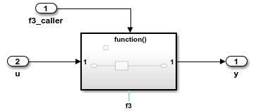
Generate code. The code generator creates the files SimulinkFunctionCaller.h and SimulinkFunctionCaller.c in the folder SimulinkFunctionCaller_ert_rtw.
SimulinkFunctionCaller.h includes the shared header file, f3.h, which contains the function entry-point declaration.
SimulinkFunctionCaller.c calls function f3.
void f3_caller(void)
{
  rtY.y = f3(rtu_u);
}
More About
See Also
Simulink Function | Function Caller