Follow Square Trajectory Using Differential (Tank) Drive
This example shows how to use the Differential (Tank) Drive block for controlling the VEX® V5 robot to follow a square trajectory.
Prerequisites
If you are new to Simulink®, watch the Simulink Quick Start video.
Complete the Getting Started with Simulink Coder Support Package for VEX EDR V5 Robot Brain example.
Required Hardware
To run this example, you need the following hardware:
VEX EDR V5 Robot Brain
V5 robot battery
Two V5 smart motors with 18:1 gear
V5 inertial sensor (recommended) or gyroscope
Smart cables and USB A to Micro cable
Connecting the Hardware
1. Connect the V5 robot battery to the VEX EDR V5 Robot Brain.
2. Connect the left smart motor to port 3 and right smart motor to port 4 using smart cables.
3. Connect the V5 inertial sensor to port 5 using smart cable. If V5 inertial sensor is not available, use gyroscope or smart motor encoders to estimate heading.
Model
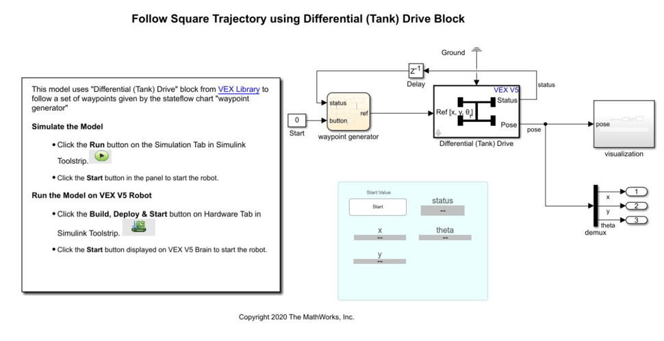
Simulink Coder™ Support Package for VEX EDR V5 Robot Brain provides a preconfigured model that you can use to get the robot to follow a set of waypoints using the Differential (Tank) Drive block.
Open the vexv5_squarepath_differential_drive_block model.
Configure the Differential (Tank) Drive Block
Double-click on the "Differential (Tank) Drive" block to open the block parameters dialog box. For more information on the block parameters, see Differential (Tank) Drive.
In the Drive tab, perform these steps.
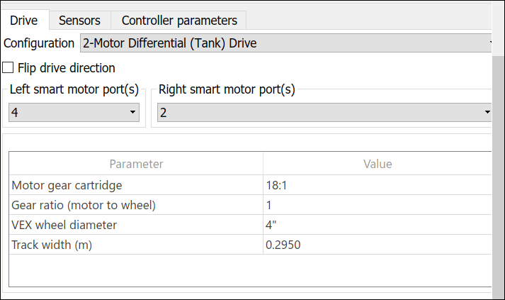
1. If the smart motors are connected to different ports, set the corresponding ports in the block.
2. If the gear ratio of smart motors is different from 18:1, select the appropriate ratio in "Motor gear cartridge" parameter.
3. If the motors are connected directly to the wheels without any gear reduction (direct drive), "Gear ratio (motor to wheel)" will be 1. Otherwise, set the gear ratio as required. For example, if wheels turn once for every two rotations of motor, then the ratio is 2/1 or 2.
4. Set the values for wheel diameter and track width.
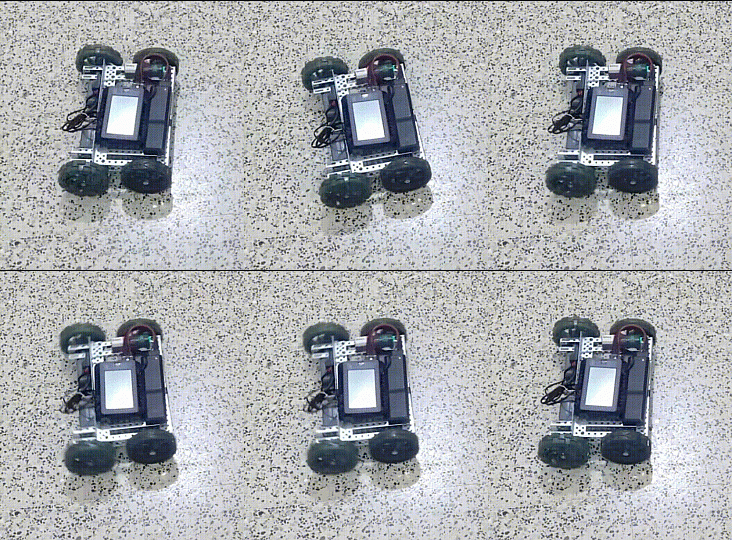
Note: When there are gears between motor and wheel, the motor and wheel might move in opposite directions. In such scenarios, select Flip drive direction parameter. Selecting incorrect setting destabilizes the heading control as shown in this image.
In the Sensors tab, perform these steps.

1. Select the sensor you are using for heading feedback. By default, Inertial sensor is selected.
2. Specify the port for Inertial or Gyroscope sensor whichever is used in the robot.
In the Controller Parameters tab, perform these steps.

Note: Controller parameters are used to set the speed and accuracy. While deploying the model for the first time, use default values.
1. Modify the Drive speed or turn rate to increase or decrease the forward movement speed and turn rate of robot.
2. Set the deadband values. Deadbands control accuracy. If you set a low value, it might cause instability with position or angle control.
3. Set the hysteresis values. Hysteresis prevents the controller from switching on and off often while driving forward.
Configure the Waypoint Follower
In the preconfigured Simulink model, the waypoints are modeled in the vexv5_square_path_differential_drive_block > waypoint generator Stateflow® chart. Double-click the waypoint generator chart to view the logic.
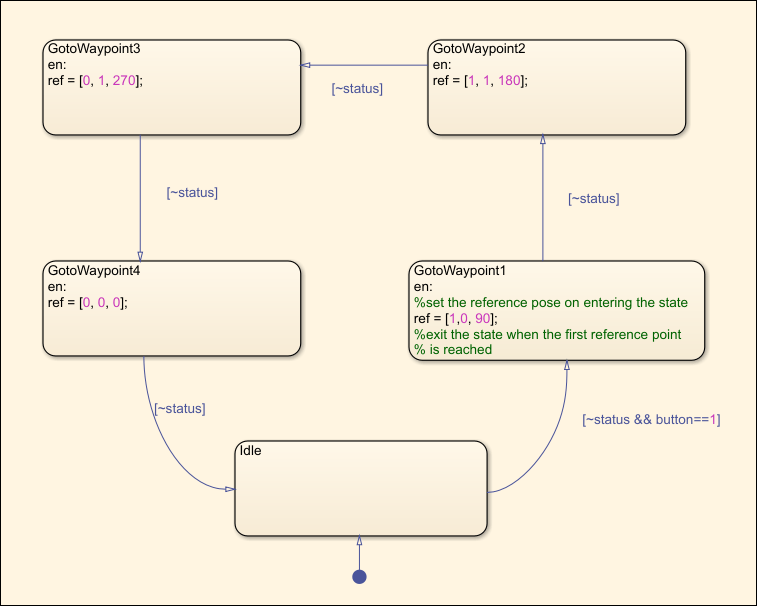
The Stateflow chart:
Waits for the user to press the start button.
Provides waypoints or reference pose to the Differential (Tank) Drive block. The chart provides waypoints as a 1-by-3 array that corresponds to the final position and final heading [X, Y, θ].
In this example model, the Stateflow chart has 4 waypoints, corresponding to a square path. If you are using this model for the first time, use the default configuration.
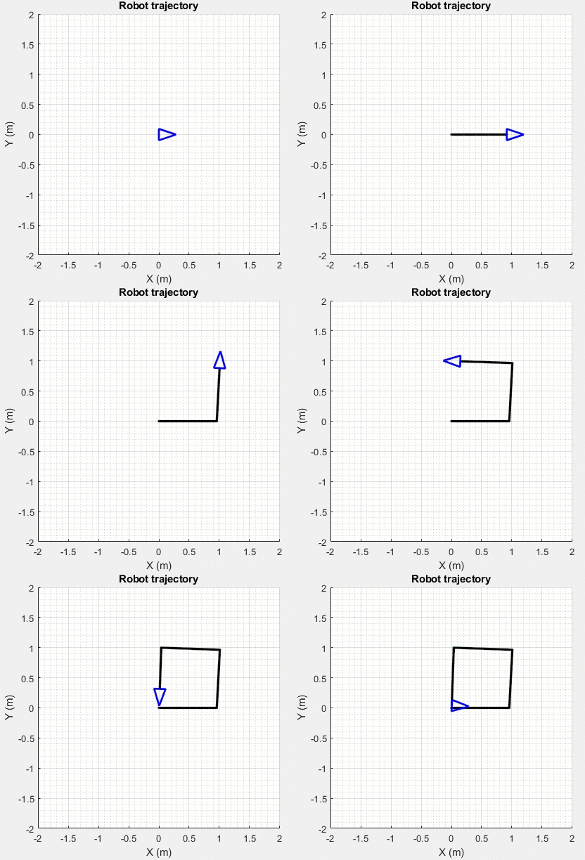
The robot remains in the idle state, until you calibrate and press the Start button. Then the robot moves to the first reference point, turns by 90 degrees, and stops. Then it moves to the second reference point, turns by 90 degrees, and stops. Similarly it moves to two more reference points to complete the square path.
Simulate Model
Note: The model supports low fidelity simulation and visualization of the robot pose (position and orientation).
1. Open the preconfigured Simulink model.
2. To simulate the model, go to the Simulation tab of the Simulink model window and click Run. The lower-left corner of the model window displays the status while Simulink prepares to run the model on the host computer.
3. Press Start button in the Simulink model to start the robot. This is a sample GIF image of the simulation.
Build and Download Simulink Model
Build the model and download it to the VEX EDR V5 Robot Brain.
1. Connect the V5 Robot Brain to your computer using the USB cable.
2. Switch on the V5 Robot Brain.
3. Open the Hardware tab and click Build, Deploy & Start. The model is deployed to the V5 Robot Brain. This action builds, downloads, and runs the model as a standalone application on the VEX V5 Robot Brain.
4. Ensure that the robot is kept steady on a level surface. This allows inertial sensor or gyroscope to calibrate when the program starts.
5. Disconnect the USB cable.
6. Once you have deployed the model, the user interface of the application shows a Start button. Keep the robot steady and press the Start button. The robot moves along a square path once and stops. If you Press the Start button again, the robot moves along a square path once more and stops. This is a sample GIF image of the robot following a square path.
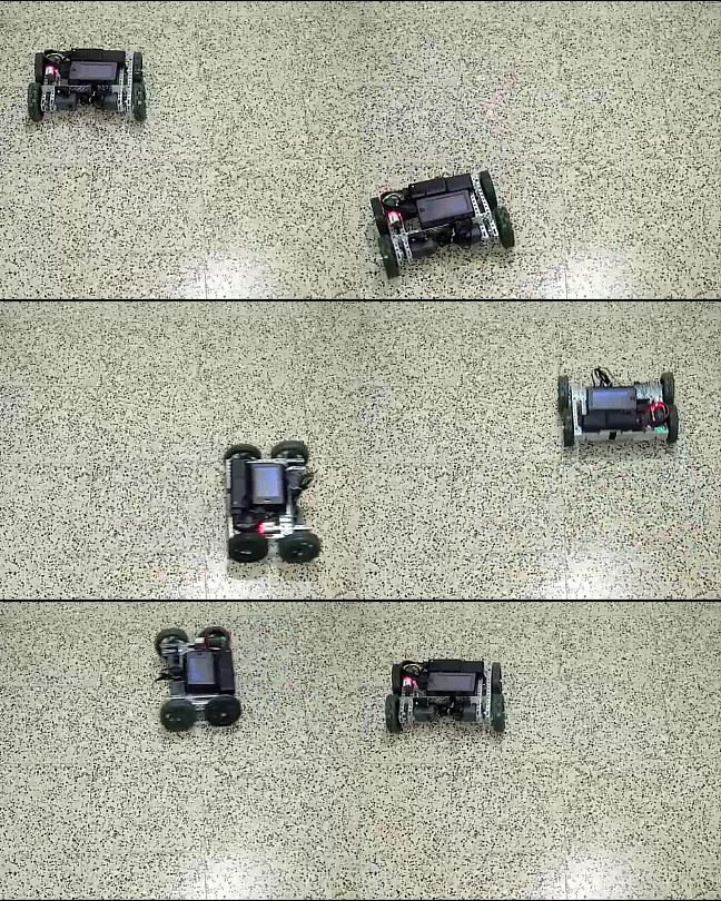
The user interface also contains display blocks to show the current status and position of the robot. A sample screen is shown here.
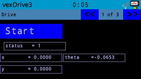
Status indicates if the drivetrain is active or not. It displays 1 when the drivetrain is active and 0 otherwise.
x and y indicates the robot's current position.
The theta value indicates the orientation angle measured in counterclockwise direction.