Satellite Link Budget
This topic provides a fundamental understanding of the satellite link budget, its importance in satellite communication, factors affecting the link budget, and derivation of the link power budget equation considering the gains and losses.
Link budget analysis is a prerequisite to design a satellite communication system, as it assists in quantifying the link performance. It involves accounting for all the power gains and losses, adding the gains and subtracting the losses that a radio frequency (RF) signal experiences within a satellite communication system. This is a simple link budget equation, to help design a proper link.
Received Power (dBm) = transmitted power (dBm) + gains (dB) – losses (dB)
Link budget calculations use power budget analysis to establish an approximate level of performance without resorting to link-level simulation. Link budget specifies the system parameters necessary to ensure that the information is received intelligibly with an adequate signal-to-noise (SNR) ratio.
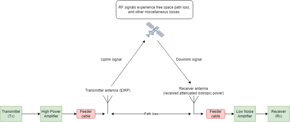
Satellite Communications Toolbox provides the Satellite Link Budget Analyzer app to perform static and time-varying link budget analysis. The app enables you to customize parameters and visualize results. You can also perform availability analysis using the app, as described by the International Telecommunication Union Recommendation (ITU-R) P.618.
Factors Affecting Link Budget
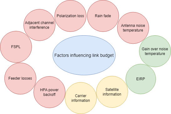
There are multiple factors that influence the satellite communication link design, but you can broadly classify the significant factors into these three groups.
Transmitter and receiver system — This includes effective isotropic radiated power (EIRP) at Tx, feeder loss on both Tx and Rx, gain over noise temperature (G/T) at Rx, high power amplifier (HPA) power backoff at the Tx, and antenna pointing loss.
In free space — This includes polarization loss experienced as a Tx-Rx pair, free space path loss (FSPL), antenna noise temperature, rain fade, and other atmospheric attenuations.
Satellite — This includes losses due to adjacent channel interference (ACI), satellite carrier spacing, satellite parameters such as orbital elements, and carrier parameters such as modulation technique used.
This figure shows the significant factors that influence a link design. The losses are indicated in red, gains are indicated in green, and the satellite specific information parameters are shown in yellow.
Let us understand these factors in detail.
EIRP
EIRP is the amount of power that would have to be radiated by an isotropic antenna to produce the equivalent power from the actual antenna in the direction with highest antenna gain.
EIRP is the total radiated power (Pt) from a transmitter antenna times the antenna gain (Gt).
EIRP = Pt ✕ Gt
If expressed in decibels:
EIRP (dBm) = Pt (dBm) + Gt (dBi)
The EIRP enables comparisons between different emitters regardless of type, size, or form.
Considering different losses such as feeder loss Lf and pointing loss Lp into account:
EIRP (dBm) = Pt (dBm) + Gt (dBi) - Lf - Lp (dB)
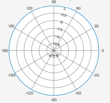
This plot shows an isotropic antenna 2-D radiation pattern for all azimuth angles at 0 degrees elevation.
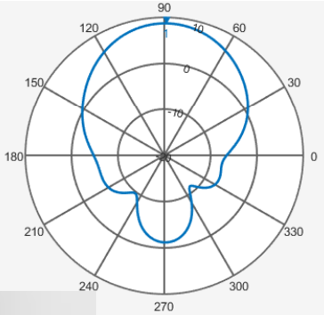
This plot shows a directional helix antenna 2-D radiation pattern with a main lobe, a back lobe, and side lobes.
Feeder Loss
This loss occurs in several components between the antenna and the receiver or the transmitter device, such as couplers, filters, and waveguides. Feeder loss is due to the resistance and imperfections in the transmission line material, which causes part of the signal energy to be dissipated as heat.
On the transmitting end, feeder losses are typically a part of the output of the high power amplifier (HPA) and the radiating antenna. Similarly, on the receiving end, feeder losses are typically a part of the output of the antenna to the input of the low noise amplifier.
FSPL
FSPL refers to the spread of the signal through space, which results in loss of the strength of the signal. Calculate FSPL using Friis transmission equation, according to which the loss is proportional to the square of the distance and the square of the frequency.
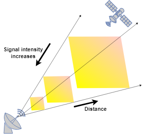
For an isotropic antenna that radiates equal power (Pt) in all directions, the power density is evenly distributed over the surface of a sphere with the isotropic antenna at its center. The intensity (I) of the signal is:
I = Pt / 4πd2,
where d is the distance between the transmitter and the receiver.
The power at the receiving antenna is Pr = I ✕ Aeff, where:
Aeff is the effective area of the receiving antenna.
Aeff = λ2/4π , where λ is the wavelength of the signal.
Substituting I and Aeff, Pr is:
,
Thus, FSPL (Lp) =
Polarization Loss
Polarization mismatch between the transmitter and the receiver antennas leads to electromagnetic (EM) power loss. EM waves are characterized by electric and magnetic fields. A basic property of plane EM waves in free-space is that the directions of the electric and magnetic field vectors are orthogonal to their direction of propagation. EM wave polarization refers to the orientation of the electric field vector.
An antenna used to receive polarized electromagnetic waves achieves its maximum output power when the antenna polarization matches the polarization of the incident electromagnetic field. Otherwise, there is polarization loss, which can lead to a degree of signal coupling, in turn causing signal degradation. Polarization can be linear, circular, or elliptical, depending on the shape traced by the electric field vector. Polarization mismatch is characterized by a polarization loss factor, which describes the fraction of incident power that has the correct polarization for reception.
When signals traverse the ionosphere, an orthogonal component can emerge, leading to depolarization. You can quantify the impact of this phenomenon through these two metrics.
Cross-polarization discrimination (XPD) — When a wave transmits with a given polarization, XPD is the ratio at the reception point of the power received with the expected polarization to the power received with the orthogonal polarization.
The cross-polarization discrimination depends both on the characteristics of the antenna and on the propagation medium.
Cross-polarization isolation (XPI) — When two radio waves transmit with the same power and orthogonal polarization, XPI is the ratio of the co-polarized power in a given receiver to the cross-polarized power in that receiver.
Raindrops contribute to depolarization as well. Ideally, a raindrop assumes a spherical shape to minimize the energy required for its cohesion. In reality, however, raindrops take on a flattened shape, resembling a spheroid with one axis longer than the others. The orientation of raindrops is randomized, influenced by factors such as wind, causing them to tilt. This tilt induces a rotation in the polarization of radio waves, which can be as much as 10 degrees. Such rotation poses a significant issue for systems using linear polarization, but it is less problematic for circular polarization, where the rotation merely adds to the existing spin of the wave.
Additionally, above the rain layer, there is often a layer of ice that can also lead to depolarization. Ice crystals typically form needle-like or plate-like shapes. Depolarization is negligible when these crystals are randomly oriented, but can occur when there is alignment.
Antenna Pointing Loss
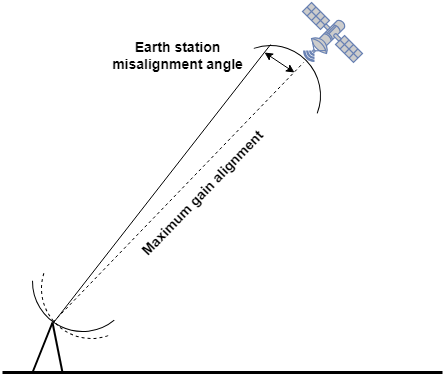
Correct alignment between an Earth station and satellite antennas provides maximum gain. Misalignment can occur either at the satellite or at the Earth station. Satellite-based misalignment must be considered during the design of the satellite, but the Earth station-based misalignment is the antenna pointing loss, and it is typically less than 1 dB. Calculating antenna misalignment losses (AML) requires statistical data, so these values are an approximation based on real data observed in several ground stations.
Along with pointing loss, misalignment loss can also be due to misalignment in the direction of polarization. These losses are quite small. Thus, antenna misalignment loss is inclusive of pointing loss as well as polarization loss.
Antenna Noise Temperature
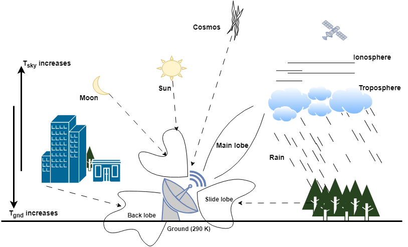
Antenna noise temperature represents the noise level an antenna produces in a given environment. This measurement is not the physical temperature of the antenna. The total noise temperature of the antenna depends mainly on sky noise (Tsky) and ground noise (Tgnd).
Tsky consists of two main components: atmospheric and background radiation. Because the upper atmosphere is an absorbing medium, the sky noise increases with elevation. Tgnd contributes dominantly to the antenna noise picked up through side lobes. Ground noise temperature increases with the decrease in elevation angle, as the side lobes intercepting the ground increase. A deep dish picks up less ground noise at lower elevations than a shallow one.
Direction of transmission also affects the antenna noise temperature. In the uplink transmission from a ground station antenna to space, the antenna temperature is quite low. For a satellite antenna transmitting downlink to the ground station antenna on Earth, the antenna temperature is around 290 K, which is the noise temperature of the Earth.
System noise temperature is the sum total of the thermal noise generated by all the components of the receiver chain, that is, the summation of antenna noise temperature and the noise contribution of the rest of the receiver system.
G/T
Antenna gain over noise temperature is a figure of merit to characterize the performance of an antenna, where G is the antenna gain, in decibels, at the receiver frequency, and T is the equivalent noise temperature of the receiving system in kelvin. T, referred to as system noise temperature, combines both antenna noise temperature and low noise amplifier (LNA) temperature.
The ratio of G and T is:
G/T = Antenna gain (dBi) – 10log(T)
HPA Power Backoff
When you feed HPA a multiple carrier signal as input, it amplifies the signal and, in the process, generates unwanted intermodulation (IM) products. When the amplifier operates in the linear region, these IM products do not interfere with the main signals. However, as the amplifier approaches the saturation point and enters the non-linear region of operation, the interference increases and these IM products start to interfere with the main signal, lowering the output signal quality. Introducing power backoff in an amplifier ensures the amplifier always operates at a power level below the saturation point in the linear region, even if the input power increases slightly. Typically, the amplifiers operate near the saturation point, as that is where efficiency is highest. You can apply power backoff at either the HPA input (known as input backoff or IBO) or at the HPA output (known as output backoff or OBO).
Rain Fade
Rainfall attenuates radio waves by scattering and absorbing energy from the wave. Rain attenuation increases with increasing frequency and is worse at Ku-band compared to C-band. Studies have shown that the rain attenuation for horizontal polarization is considerably greater than for vertical polarization. The link margin must compensate for a rain fade. In normal conditions, only oxygen and water vapour significantly contribute to absorption, but other atmospheric gases become a factor in very dry air conditions at frequencies above 70 GHz. International Telecommunication Union Recommendation (ITU-R) P.618 predicts the various atmospheric propagation parameters necessary in the planning of Earth-space networks. For details, see Earth-Space Propagation Losses.
Satellite Information
This includes information related to satellite aspects such as orbital position, received G/T obtained from satellite operators or G/T contour maps, and saturation flux density. This information helps effectively calculate a satellite link budget.
Carrier Information
This includes information such as user data rate in megabits per second (Mbps), type of modulation technique used, forward error correction (FEC) code rate, roll off factor, and bit error rate (BER). This information helps to analyze the link budget for a space-to-ground link and the inverse.
Satellite Carrier Spacing
The level of ACI is a function of several parameters: orbital separation between the desired and the interfering satellites, antenna side lobe performance of the interfering uplink Earth station, antenna side lobe performance of the receiving Earth station, and spectral power density of the carriers.
If the satellite carrier spacing is less than the recommended spacing, a spectral overlap from the adjacent carriers into the desired carrier is possible. At the demodulator, this unwanted energy acts as increased noise, reducing the effective carrier-to-noise ratio (CNR), C/N0, and degrading the BER.
Link Power Budget Equation
The goal of radio link design is to ensure that you can establish a reliable communication link between a radio transmitter and its associated receiver. Link performance is typically assessed by the ratio of the received carrier power C to the noise power spectral density No, expressed as the C/No ratio.
Define carrier power as the receiver input power.
C = PR
(Equation 1)
where:
PT = Transmitter power in watts
GT = Antenna gain at transmitter
LT = Loss due to misalignment of transmitter antenna
LFT = Feeder loss between the transmitter and the antenna at transmitting end
LP = Propagation loss, which includes FSPL and atmospheric attenuation
GR = Antenna gain at receiver
LR = Loss due to misalignment of receiver antenna
LFR = Feeder loss between the antenna at receiving end and the receiver
LPol = Polarization mismatch loss
All gains and losses are in linear scale.
Define noise spectral density as the product of the Boltzmann constant k and system noise temperature Ts.
N0 = k ✕ Ts (Equation 2)
where:
k = Boltzmann's constant = 1.38*10-23 (J/K)
Ts includes the noise generated by the antenna and the feeder along with the receiver noise.
Ts = Tant + Tr,
where:
Tant = Tsky + Tgnd, where:
Tsky includes noise from the atmosphere.
Tgnd includes noise from the side lobes and back lobe.
Tr includes noise contribution of the receiver.
Calculate C/No using equations 1 and 2:
(Equation 3)
You can interpret the C/No expression as:
C/No = (EIRP)✕(1/L)✕(Composite receiver gain/noise temperature)✕(1/k) (Equation 4)
where:
EIRP is at the transmitter end in watts
L denotes the total path loss in the transmission medium
(Composite receiver gain/noise temperature) is G/T, or the figure of merit of the receiver
C/No is expressed in hertz
You can further simplify equation 4 as:
C/No = (EIRP)✕(1/Path loss)✕(G/T)✕(1/k)
Using the decibel representation (dB):
where:
LTx = Sum of all losses at transmitter end
LRx = Sum of all losses at receiver end
This gives us the link power budget equation.
One important consideration in link design is link margin. Because the instantaneous signal and noise powers at the receiver front end can fluctuate, you must apply link margin to attempt to counteract the power fluctuations. This ensures the link design meets a given data integrity requirement, typically expressed as BER. To achieve a target BER for a modulation scheme, correctly set the required Eb/No.
Received Eb/No = C/No – 10log10(user bit rate) – 60
where:
Received Eb/No = Received energy per bit to noise power density ratio in dB
User bit rate = Bit rate of the link in megabits per second (Mbps)
Using the value of received Eb/No, calculate the link margin using this formula.
Margin = Received Eb/No – Required Eb/No