Main Content

satelliteCNR

Carrier-to-noise ratio for configured satellite link budget parameters

Since R2022b

    Description

    [cn,info] = satelliteCNR(cfg) computes the carrier-to-noise ratio (CNR) cn for the satellite link budget parameters specified in the configuration cfg. The function also returns the intermediate results in the CNR calculation info based on the link budget parameters specified in cfg.

    example

    Examples

    collapse all

    Calculate the CNR and the received link margin for the specified link budget parameters.

    Create a default CNR configuration object, and then set its properties.

    cfg = satelliteCNRConfig;
    cfg.TransmitterPower = 17;               % in dBW
    cfg.TransmitterSystemLoss = 9;           % in dB
    cfg.TransmitterAntennaGain = 38;         % in dBi
    cfg.Distance = 40215;                    % in km
    cfg.Frequency = 11;                      % in GHz
    
    % Here, miscellaneous losses include polarization loss, interference 
    % loss, and antenna mispointing loss, respectively.
    polLoss = 3.0103;
    intLoss = 2;
    antLoss = 1;
    cfg.MiscellaneousLoss =  polLoss + intLoss + antLoss; % in dB
    cfg.GainToNoiseTemperatureRatio = 25;                 % in dB/K
    cfg.ReceiverSystemLoss = 2;                           % in dB
    cfg.BitRate = 10;                                     % in Mbps

    Display the CNR configuration object properties.

    disp(cfg)
      satelliteCNRConfig with properties:
    
                   TransmitterPower: 17
              TransmitterSystemLoss: 9
             TransmitterAntennaGain: 38
                           Distance: 40215
                          Frequency: 11
                  MiscellaneousLoss: 6.0103
        GainToNoiseTemperatureRatio: 25
                 ReceiverSystemLoss: 2
                            BitRate: 10
                         SymbolRate: 10
                          Bandwidth: 6
    

    Calculate the CNR.

    [cn,info] = satelliteCNR(cfg)
    cn = 
    18.4440
    
    info = struct with fields:
                   TransmitterEIRP: 46
                              FSPL: 205.3634
            ReceivedIsotropicPower: -165.3737
        CarrierToNoiseDensityRatio: 86.2255
                      ReceivedEbNo: 16.2255
                      ReceivedEsNo: 16.2255


    Compute the link margin. Assume a required energy per bit to noise power density ratio (Eb/No) of 10 dB and an implementation loss of 2 dB in the receiver.

    reqEbNo = 10;
    implLoss = 2;
    margin = info.ReceivedEbNo - reqEbNo - implLoss
    margin = 
    4.2255
    

    Input Arguments

    collapse all

    CNR configuration object, specified as a satelliteCNRConfig object.

    Output Arguments

    collapse all

    Carrier-to-noise ratio in dB, returned as a scalar. For more information, see Algorithms.

    Data Types: double

    Intermediate results in the CNR calculation, based on the link budget parameters specified in the configuration object cfg returned as a structure with these fields.

    For more information, see Algorithms.

    Structure FieldDescription
    TransmitterEIRP

    Effective isotropic radiated power (EIRP) of the transmitter antenna, returned as a scalar. Value is in dBW.

    FSPL

    Free space path loss (FSPL) from the transmitter to the receiver antenna, returned as a scalar. Value is in dB.

    ReceivedIsotropicPower

    Received isotropic power at the receiver antenna, returned as a scalar. Value is in dBW.

    CarrierToNoiseDensityRatio

    Carrier-to-noise power density ratio (C/No), returned as a scalar. Value is in dB-Hz.

    ReceivedEbNo

    Received energy per bit to noise power density ratio (Eb/No), returned as a scalar. Value is in dB.

    ReceivedEsNo

    Received energy per symbol to noise power density ratio (Es/No), returned as a scalar. Value is in dB.

    All fields in the structure are of data type double.

    Data Types: struct

    Algorithms

    The CNR for a satellite communications system measures the strength of the carrier signal at a receiver relative to the strength of the noise at that receiver. This diagram shows the various signal losses and gains involved in satellite communications.
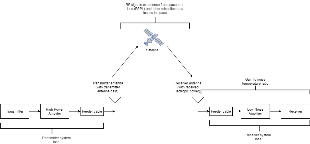
    Losses and gains in a satellite communication system. Transmitter system loss occurs between the transmitter, high power amplifier, and feeder cable, followed by gain at the transmitter antenna. The RF signals then experience free space path loss and miscellaneous losses in space, traveling to and from the satellite. Finally, once the signal reaches the receiver antenna, it experiences further losses, through the feeder cable and low noise amplifier, to the receiver.

    To compute the CNR cn for a system, the satelliteCNR function performs various intermediate calculations, using the properties of the satelliteCNRConfig configuration object, and outputs them to a structure, info. The function uses these formulas for the intermediate calculations.

    info Structure FieldFormula
    TransmitterEIRP

    TransmitterPowerTransmitterSystemLoss + TransmitterAntennaGain

    FSPL

    20*log10(4*π*Distance*Frequencyphysconstant("LightSpeed"))

    ReceivedIsotropicPower

    TransmitterEIRP - FSPL - MiscellaneousLoss

    CarrierToNoiseDensityRatio

    ReceivedIsotropicPower + GainToNoiseTemperatureRatio - 10*log10(physconstant("Boltzmann")) - ReceiverSystemLoss

    ReceivedEbNo

    CarrierToNoiseDensityRatio - 10*log10(BitRate) - 60

    ReceivedEsNo

    CarrierToNoiseDensityRatio - 10*log10(SymbolRate) - 60

    The function then computes the carrier-to-noise ratio using this formula:

    cn = CarrierToNoiseDensityRatio - 10*log10(Bandwidth) - 60

    Extended Capabilities

    C/C++ Code Generation
    Generate C and C++ code using MATLAB® Coder™.

    Version History

    Introduced in R2022b