Satellite Scenario Key Concepts
The Satellite Communications
Toolbox
satelliteScenario object provides the ability to model and visualize
satellites in orbit, compute access with ground stations, and visualize and analyze
communication links. This topic provides an overview of the technical terms frequently
encountered in scenario visualization.
You can use the Mapping Toolbox™
3-D Coordinate and Vector Transfomations to transform coordinates and
vector components between global and local systems.
Coordinate Systems
Geodetic Coordinates
A geodetic system uses coordinates (lat, lon, h) to represent position relative to a reference ellipsoid. All geodetic coordinates in a satellite scenario use the World Geodetic System, 1984 (WGS 84), as the reference ellipsoid. The coordinate origin of WGS 84 is located at the center of mass of the Earth.
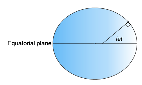
lat is the latitude, which originates at the equator. More specifically, the latitude of a point is the angle normal to the ellipsoid at that point makes with the equatorial plane, which contains the center and equator of the ellipsoid. An angle of latitude is in the range [–90°, 90°]. Positive latitudes correspond to North and negative latitudes correspond to South.
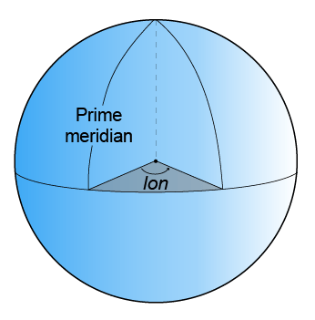
lon is the longitude, which originates at the prime meridian. More specifically, the longitude of a point is the angle that a plane containing the ellipsoid center and the meridian containing that point makes with the plane containing the ellipsoid center and prime meridian. Positive longitudes are measured in a counterclockwise direction from a vantage point above the North Pole. Typically, longitude is in the range [–180°, 180°] or [0°, 360°].
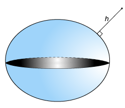
h is the ellipsoidal height, which is measured along a normal of the reference spheroid.
Earth-Centered Earth-Fixed Coordinates
An Earth-centered Earth-fixed (ECEF) system uses Cartesian coordinates (X, Y, Z) to represent position relative to the center of the reference ellipsoid. The distance between the center of the ellipsoid and the center of the Earth depends on the reference ellipsoid. The Satellite scenario uses the WGS 84 reference ellipsoid, which has a center that coincides with the center of mass of the Earth.
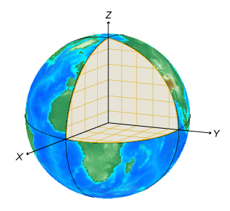
The positive X-axis intersects the surface of the ellipsoid at 0° latitude and 0° longitude, where the equator meets the prime meridian.
The positive Y-axis intersects the surface of the ellipsoid at 0° latitude and 90° longitude.
The positive Z-axis intersects the surface of the ellipsoid at 90° latitude.
Note
Alignment of boundaries and region labels are a presentation of the feature provided by the data vendors and do not imply endorsement by MathWorks®.
Frame of Reference and North East Down (NED) Frame
To describe a point in space, you need a frame of reference that does not rotate with respect
to the stars. The Geocentric Celestial Reference Frame
(GCRF), with the origin at the center of the Earth and orthogonal
vectors I, J, and
K, is used as the frame of reference when you
add Satellite objects to a satelliteScenario object. The fundamental plane
is the IJ-plane, which is closely aligned with the
equator with a small offset that changes over time because of precession and
nutation of the rotation axis of the Earth. When you use orbital elements to add
satellites to the satellite scenario, the coordinates are assumed to be defined in
the geocentric celestial reference frame.
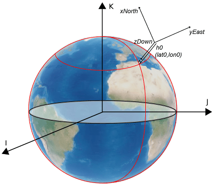
When you refer to the position, velocity, acceleration, orientation, and angular velocity, you must mention the coordinate system in which these quantities are expressed. Global systems such as GCRF and geodetic systems describe the position of an object using a triplet of coordinates. Local systems such as NED and Azimuth Elevation Range (AER) systems require two triplets of coordinates: one triplet describes the location of the origin, and the other triplet describes the location of the object with respect to the origin.
An NED system uses Cartesian coordinates (xNorth, yEast, zDown) to represent position relative to a local origin. The local origin is described by geodetic coordinates (lat0, lon0, h0). Typically, the local origin of an NED system is above the surface of the Earth.
The positive xNorth-axis points North along the meridian of longitude containing lon0.
The positive yEast-axis points East along the parallel of latitude containing lat0.
The positive zDown-axis points Down along the ellipsoid normal.
An NED coordinate system is commonly used to specify location relative to a moving satellite. In this case, the coordinates are not fixed to the frame of the satellite, but to the point on the surface of the WGS 84 ellipsoid corresponding to the latitude and longitude of the satellite.
Roll, Pitch, and Yaw
Three lines run through a satellite and intersect at right angles at the center of mass of the satellite. These axes are fixed with respect to the satellite and are used to define the orientation of the satellite with respect to the NED frame. The orientation is defined by rotations in this sequence:
Rotation about the yaw axis by the yaw angle
Rotation about the pitch axis by the pitch angle
Rotation about the roll axis by the roll angle

The yaw, pitch, and roll angles have positive clockwise directions when looking in the positive direction of the axes. Unless otherwise specified, the Satellite Communications Toolbox uses the yaw-pitch-roll rotation order for these angles by default.
Azimuth-Elevation-Range (AER) Coordinates
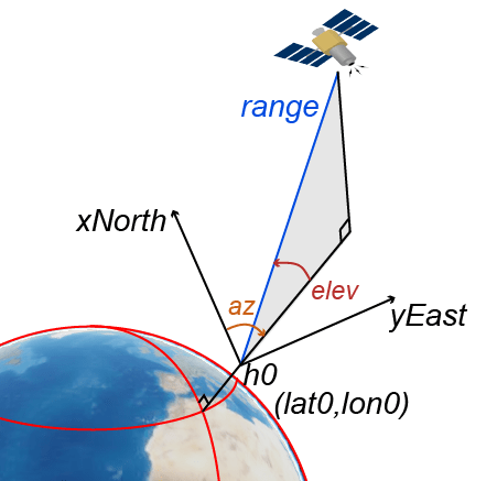
An AER system uses spherical coordinates (az, elev, range) to represent position relative to a local origin. The local origin is described by geodetic coordinates (lat0, lon0, h0). Azimuth, elevation, and slant ranges are dependent on a local Cartesian system (for example, an NED system) with the origin centered at the center of mass of the satellite.
az is the azimuth, which is the clockwise angle in the (xNorth)(yEast)-plane from the positive xNorth-axis to the projection of the object into the plane.
elev is the elevation, which is the angle from the (xNorth)(yEast)-plane to the object.
range is the slant range, which is the Euclidean distance between the object and the local origin.
Orbital Elements
Orbital elements are parameters required to uniquely identify a specific orbit. Uniquely defining an orbit and the position of a satellite within satellite orbit requires at least six parameters. Three of the parameters describe what the orbital plane looks like and the position of the satellite in the ellipse. The other three parameters describe how that plane is oriented in the celestial inertial reference frame and the location of the satellite in that plane. These six parameters are called the Keplerian elements or orbital elements.
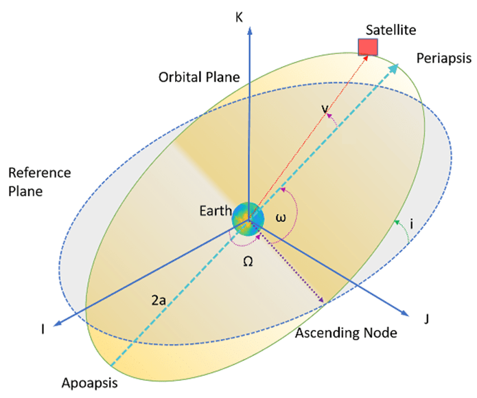
In this diagram, the orbital plane (yellow) intersects a reference plane (gray). For Earth-orbiting satellites, the reference plane is usually the IJ-plane of the GCRF.
These two elements define the shape and size of the ellipse:
Eccentricity (e) — Describe how elongated the shape of the ellipse is when compared to a circle.
Semimajor axis (a) — The sum of the periapsis and apoapsis distances divided by 2. Periapsis is the point at which an orbiting object is closest to the center of mass of the body it is orbiting. Apoapsis is the point at which an orbiting object is farthest away from the center of mass of the body it is orbiting. For classic two-body orbits, the semimajor axis is the distance between the centers of the bodies.
These two elements define the orientation of the orbital plane in which the ellipse is embedded:
Inclination (i) — The vertical tilt of the ellipse with respect to the reference plane measured at the ascending node. The ascending node is the location where the orbit passes upward through the reference plane (the green angle i in the diagram). The tilt angle is measured perpendicular to the line of intersection between orbital plane and the reference plane. Any three points on an ellipse defines the ellipse orbital plane.
Starting with an equatorial orbit, the orbital plane can be tilted up. The angle it is tilted up from the equator is referred to as the inclination angle, i, in the range [0,180]. Because the center of the Earth must always be in the orbital plane, the point in the orbit where the satellite passes the equator on its way up north-bound through the orbit is the ascending node, and the point where the satellite passes the equator on its way down south-bound is the descending node. Drawing a line through these two points on the equator defines the line of nodes.
Right ascension of ascending node (Ω) — RAAN is the angle between GCRF X-axis and ascending node. RAAN is always constant if using two body Keplerian propagation model and there are no other perturbing forces When there is no perturbation, the orbit stays the same in space and the vernal equinox is the X axis of GCRF and the ascending node does not move. So the RAAN stays the same. The rotation of the right ascension of the ascending node (RAAN) can be any number between 0° and 360°.
Longitude of ascending node (LAN) — LAN for geosynchronous satellites) refers to the geographic longitude or the angle between the international terrestrial reference frame (IRTF) x axis and the ascending node. In LAN, the X-axis is the line through the equator and Greenwich meridian. To calculate LAN, you can also use
RAAN - GMST, where GMST is Greenwich Meridian Sidereal Time. As Earth rotates, this X axis also rotates with it. and LAN is not constant. For geosynchronous satellites, by the time the spacecraft is back to the ascending node, the X axis is also back to its original location, so LAN appears as a constant.
The remaining two elements are:
Argument of periapsis (ω) — The orientation of the ellipse in the orbital plane, as an angle measured from the ascending node to the periapsis in the range [0, 360).
True Anomaly (v) — The position of the orbiting body along the ellipse at a specific time. The position of the satellite on the path is measured counterclockwise from the periapsis and is called the true anomaly, ν, in the range [0, 360).
Two Line Element (TLE) Files
The Satellite Communications
Toolbox satellite function accepts a TLE file as a possible input to initialize the satellite. To download TLE files, see the Space track website.
A TLE set is a data format encoding a list of orbital elements of an Earth orbiting object for a given point in time, the epoch. Orbital element parameters can be encoded as text in a variety of formats. The most common format is the National Aeronautics and Space Administration (NASA) or North American Aerospace Defense Command (NORAD) TLE format. In this format, each satellite has three rows: the first row contains the name of the satellite, and the next two rows are the standard TLE.
Data for each satellite consists of three lines, as this example shows.
Satellite 1
1 25544U 98067A   04236.56031392  .00020137  00000-0  16538-3 0  9993
2 25544  51.6335 344.7760 0007976 126.2523 325.9359 15.70406856328906
Row 1 is an eleven-character satellite name.
Rows 2 and 3 are the standard TLE set format identical to that used by NORAD and NASA.
This table describes the columns in row 2.
Column Description Example 1 Line number
13–7 Satellite number
255448 Elset classification
U10–17 International designator
98067A19–32 Element set epoch (UTC)
04236.5603139234–43 First derivative of the mean motion with respect to time
.0002013745–52 Second derivative of the mean motion with respect to time (decimal point assumed)
00000-054–61 BSTAR drag term
16538-363 Element set type
065–68 Element number
99969 Check sum (modulo 10)
3This table describes the columns in row 3.
Column Description Example 1 Line number of element data
23–7 Satellite number
255449–16 Inclination (in degrees)
51.633518–25 Right ascension of the ascending node (in degrees)
344.776027–33 Eccentricity (leading decimal point assumed)
000797635–42 Argument of perigee (in degrees)
126.252344–51 Mean anomaly (in degrees)
325.935953–63 Mean motion (in revs per day)
15.7040685664–68 Revolution number at epoch (in revs)
3289069 Check sum (modulo 10)
6
Depending on the application and object orbit, the data derived from TLEs older than 30 days can become unreliable. Calculate the orbital positions from TLEs using the Simplified General Perturbations-4 (SGP4) and Simplified Deep-Space Perturbations-4 (SDP4) algorithms.
System Effectiveness Model (SEM) Almanac
The Satellite Communications
Toolbox
satellite function accepts a SEM Almanac file as a
possible input to initialize the satellite. To download SEM files, see the https://www.navcen.uscg.gov/gps-nanus-almanacs-opsadvisories-sof
website.
Almanac files are simplified guides used by GPS and other satellite navigation systems to find and use satellites. These files contain basic information about the location and status of each satellite in the constellation. Almanac files are not as detailed or precise as TLE files. But the data in the almanac files are regularly updated to keep this information current, supporting efficient navigation and communication across the globe. SEM format of the almanac files are primarily used as input for software tools.
Orbit Mean-Elements Message (OMM) File
Satellite Communications
Toolbox accepts Orbit Mean-Elements Message (OMM) files as inputs to
satellite. OMM files are part of Orbit Data Messages (ODM) Recommended
Standard CCSDS 502.0-B-2 developed by The Consultative Committee for Space Data Systems
(CCSDS). OMM files enable you to access general perturbations (GP) data using standard
queries. To download OMM files, visit the Space track or CelesTrak websites. Satellite Communications
Toolbox supports the .XML and .JSON
OMM file formats.
OMM file formats are defined by CelesTrak®. For more information, see Orbit Data Messages.
Satellite Communications Toolbox uses these fields of the OMM file. All other fields are ignored.
| Predicate | Description | Examples |
|---|---|---|
| Satellite names. |
|
| Mean element theory. This value must be
|
|
| Mean Keplerian elements epoch. |
|
| Mean motion (rev/day). |
|
| Eccentricity. |
|
| Inclination, in degrees. |
|
| Right ascension of ascending node, in degrees. |
|
| Pericenter argument, in degrees. |
|
| Mean anomaly, in degrees. |
|
| NORAD catalog number (satellite number). |
|
| SGP/SGP4 drag-like coefficient in 1/Earth radii. |
|
References
[1] “Basics of Space Flight” https://solarsystem.nasa.gov/basics/chapter5-1/.
[2] “CelesTrak. Frequently Asked Questions: Two-Line Element Set Format.” Accessed March 26, 2016. https://celestrak.com/columns/v04n03/.
See Also
Objects
Functions
show|play|hide|satellite|access|groundStation|satelliteScenarioViewer|conicalSensor|transmitter|receiver
Topics
- Multi-Hop Satellite Communications Link Between Two Ground Stations
- Satellite Scenario Basics
- Satellite Constellation Access to Ground Station
- Comparison of Orbit Propagators
- Modeling Satellite Constellations Using Ephemeris Data
- Estimate GNSS Receiver Position with Simulated Satellite Constellations
- Model, Visualize, and Analyze Satellite Scenario