Best Practices for Modeling Pulley Networks
A closed-network pulley system relies on belt tension to convey forces throughout the network. The weight of the belt adds inertia to the system when the belt is in motion. In Simscape, you can model pulley networks with the Belt Pulley block, which uses belt tension and inertia to simulate motion and the distribution of forces. Like a physical pulley, the block requires tension at both ends when operating. However, because the block has inherent directionality, you must align the positive and negative velocity ports with each other and correctly orient each block.
To initialize your system and orient the blocks:
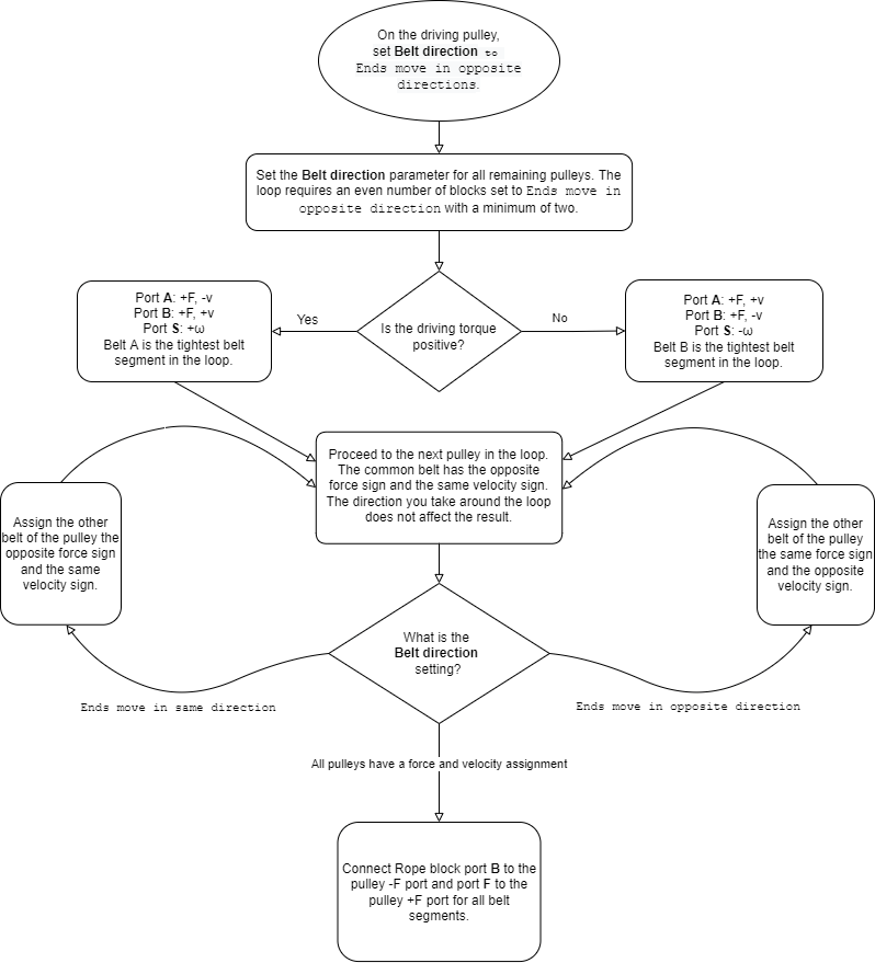
Set the Belt direction for each Belt Pulley block in the loop to obtain a non-trivial solution.
Obtain a physically accurate direction of rotational velocity, ω, for a given pulley.
Orient the Rope blocks between pulleys to transfer the correct tension.
This flow chart shows an overview of the process. The flow chart assumes the pulley network has one torque source, the driving pulley.

You cannot specify a rotational velocity or torque for each pulley in the network. By tracking the force and velocity direction for each Belt Pulley and Rope block in the network, you can ensure that your model generates physical results.
The Power Window System example shows a detailed pulley network model that you can adjust.
Belt Direction
Belt direction is a pulley sign convention that is not constrained by physics or
geometry. For a Belt Pulley block with the
Belt direction parameter set to Ends move in
opposite direction, the velocities at port A
and port B have opposite signs that depend on the sign of the
angular velocity, ω, at port S.

For a Belt Pulley block with Belt
direction set to Ends move in same
direction, the velocities at port A and port
B have the same signs. The signs of the ports depend on the
sign of the angular velocity at port S.

To change the sign of the rotational velocity for a Belt Pulley block, change the setting of the Belt direction parameter.
Belt Direction in Closed Pulley Networks
To obtain a nonzero response in a closed-loop system with two pulleys, set
Belt direction to Ends move in opposite
direction. When dealing with three or more pulleys, ensure the
loop has an even number of Belt Pulley blocks
with the Belt direction parameter set to Ends
move in opposite direction. To check whether the
Belt direction parameter is responsible for trivial
simulation results, choose Ends move in same
direction. If there are no problems with the pulley network,
the simulation generates non-trivial results when you complete this step. The
figure demonstrates a pulley loop with an even number of Belt
Pulley blocks using the Ends move in opposite
direction setting.

Rope Block Tension
Maintain belt contact by including Rope blocks in your pulley system. You need at least one fewer Rope blocks than the number of pulley pairs, at a minimum. For example, if there are five pulley pairs, include at least four Rope blocks. You can confirm that the belts start and remain in tension by using the Simscape Results Explorer. To configure your system such that all Rope blocks have positive, stable tension at the start of simulation:
Determine the sign of the force for each node of each Belt Pulley block.
Add Rope blocks between each Belt Pulley block. Connect port F of the Rope block to the positive force end of the Belt Pulley block.
Compare your results for rope tension with your expectation for a real system.

Inertia
To facilitate motion, include inertia in the pulley system. You can include inertia in a Belt Pulley block by specifying a nonzero value for the Inertia parameter in the block configuration settings. Another way to include inertia is to add a downstream inertia source from the Simscape™ Driveline™ Inertias and Loads library or from the Rotational Elements library. Attribute some initial velocity to the inertia, as needed, to initiate motion in your pulley system.
You can also add mass to the tensioning device to aid with numerical
initialization. If you are using the Cable block as
a tensioning device, set Model mass to
On.
See Also
Belt Drive | Belt Pulley | Cable | Rope Drum