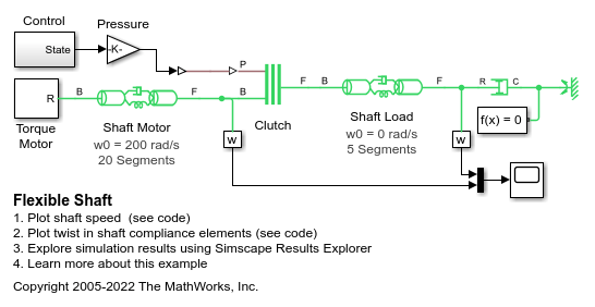
Flexible Shaft
This example shows two flexible aluminum shafts modeled using a lumped parameter approach. Both shafts consist of 20 segments containing inertias, damping, and stiff torsional springs. At the start of the simulation, the clutch is unlocked and the driven shaft is free. Note that the initial velocity of the motor shaft is set to 200 rad/s and that the system starts at steady state. The clutch engages and disengages during the test, and during each event the effect of the shaft flexibility can be seen in the simulation results.
Model

Simulation Results from Simscape Logging
The plots below show the rotational speed of two flexible shafts as a clutch between them is locked and unlocked. The motor shaft is driven by a motor, and the load shaft is connected to a viscous damper. The oscillations triggered by the sudden engaging and disengaging of the clutch are due to the flexibility in the shafts.

The plots below show the amount of twist in each compliance element of the flexible shafts as a clutch between them is locked and unlocked. Though the stiffness and dimensions are the same for each shaft, their behavior is slightly different because they are subjected to different loads. The motor shaft is driven by a motor, and the load shaft is connected to a viscous damper.
