Vehicle with Manual Transmission
This example shows a vehicle that has a four-speed manual transmission. The key elements of the transmission are four synchronizers. By engaging or disengaging these synchronizers and associated dog clutches, the transmission provides four ratios 3.581, 2.022, 1.384, and 1, respectively. The synchronizers are modeled using the Cone Clutch and Dog Clutch blocks.
The model also provides an abstracted representation of the gearbox that is significantly less complex and thus simulates much faster. It uses simply a variable ratio gear to represent the various gear ratios in the detailed transmission, plus a clutch to represent neutral. By eliminating nearly all of the discontinuities, it is designed for hardware-in-the-loop simulation. To select this variant, use the hyperlinks in the model.
The model supports automatic and manual driver modes. In manual driver mode, you use Simulink Dashboard blocks to control the gearbox shifting and synchronization. Manual: To run the model in manual driver mode, click on the "Manual" hyperlink. Hyperlink activates the sliders, sets the simulation pacing to '1' and sets the simulation time to 'inf'. For the start put the Gear lever dashboard G1, Accelerator pedal and Brake pedal to '0' and start the simulation. During simulation, each gear shift can be a single gear shift or multiple gear shifts. Use the sliders to adjust the accelerator pedal and brake pedal. In manual mode gear shifting should be done based on vehicle speed as abrupt gear shifting can cause engine speed errors.
Auto: Auto is the default mode for simulation. To run the model in auto mode, click on the "Auto" hyperlink. Hyperlink de-activates the sliders for the pedals, it disables the simulation pacing and sets the simulation time to 100 sec which is the velocity profile time length in the signal editor. Velocity from different mat files can be loaded and simulation time needs to be changed accordingly. During simulation, a PI controller representing the driver adjusts the throttle and brake in response to a requested vehicle velocity provided by a Signal Editor block. An automatic gear shifter implemented in Stateflow® shifts the gear based on gear speed limits, which are set in the Model pre-load function.
Control is set for 4 gear transmission in auto mode as default.
Model

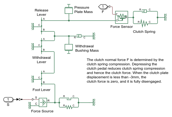
Clutch Pedal Linkage Subsystem

Abstract Transmission Variant
This is the simplified version of the transmission. Using a variable ratio gear that accepts the gear ratio as an input signal, we remove nearly all of the discontinuities. When properly tuned, it can match the results of the detailed variant.

Detailed Transmission Variant
This is the detailed version of the transmission. It contains all the gears plus the dog clutches and cone clutches. This variant provides very accurate results and is perfect for tuning control algorithms and estimating fuel economy.

Synchronizer 1 Subsystem
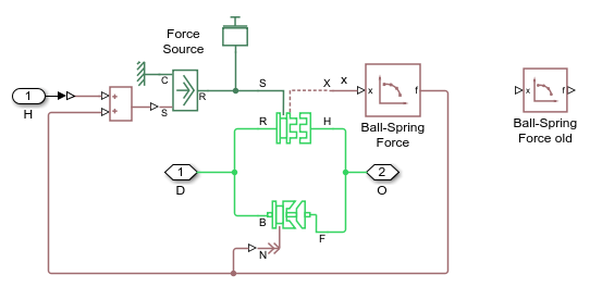
This subsystem implements a customized model of a synchronizer. Here, the structure of the synchronizer can be seen and modified. Simscape™ Driveline™ also provides pre-built single and double-synchronizer blocks.

Gear Control Subsystem
This subsystem implements a logic for auto transition of gear. The logic is implemented in Stateflow, it has three parallel flows for gear up/down shift, velocity limit calculation for gear shifting and gear state flow to give the current gear.

Vehicle Body Subsystem
This subsystem implements the longitudinal vehicle dynamics and the tire model. It is sufficient for running drive cycles to estimate fuel economy and to tune transmission control algorithms.

Simulation Results from Simscape Logging
The plots below show the driver inputs to the engine and transmission. The top plot shows the forces applied to the synchronizers to select the active gear, and the bottom plot shows the inputs to the throttle and clutch.

The plot below show the speeds of various shafts in the drivetrain. The output shaft speed is equal to the speed of the gear whose synchronizer is engaged. The engine stays in appropriate speed range even though the vehicle is accelerating because of the chosen gear.

The plot below show the behavior of the abstract models and the detailed model. The results are very similar, indicating that the abstract models can be used without a significant loss of accuracy.
