Stackup and Extraction Control in Serial Link Project
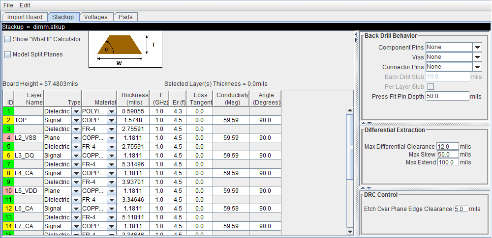
The Stackup tab of the Import & Setup Board dialog shows the stackup from the PCB Database and allows for extraction control for padstack, differential traces, and DRC.
The tab is divided into two areas: Stackup Editor and Extraction Control. The Stackup Editor on the left side of the tab shows the stackup that was read from the PCB Database and allows the override of the auto-generated stackup thicknesses, material properties, and trapezoidal angle as well as the ability to do “What If” exploration and select whether to model discontinuities associated with etches crossing split planes. The right side of the tab controls the padstack backdrill options, differential extraction, and DRC control.

Stackup Editor
The Stackup Editor displays one row for each signal, plane, and dielectric layer in the stackup. Parameter values can be changed if desired by typing new values into the table cells. The stackup data plus the trace width data are used by the field solver to create lossy transmission line models for post-layout nets.
Each layer must be defined as either Dielectric,
Mixed, Plane, or
Signal in the stackup column called
Type. Signal layers can be either type
Mixed or Signal. The
Mixed designation is provided primarily for boards and packages
where sections of the signal layer may contain small planes for impedance control. In most
cases the Signal designation would be sufficient, but it is
important to carefully review the board layout and identify cases where
Mixed may be required.
Checking Model Split Planes enables modeling of discontinuities associated with etches crossing over splits in planes. The change in trace cross-section results in an impedance change in the model.
Checking Table-Driven Loss Model allows a table-driven loss model to be used. When checked, the list contains the names of imported loss models and the item Assign Per Layer Loss Model. When a loss model is selected, it is used for all layers in the stackup. If Assign Per Layer Loss Model is selected, from the list the Table-Driven Loss Model column appears in the stackup with a list to choose the loss model for each signal layer.
You may use the Stackup Editor as a calculator to compute trace impedance based upon the width and separation. To use the calculator:
Check the Show “What If” Calculator check box to display the calculator columns
Enter one or more values in the appropriate cells followed by the tab key
Click Calculate
This uses the stackup data with the Desired Width and Desired Separation values to calculate the single-ended and differential impedance for that layer.
Extraction Control
The Extraction Control section of the tab controls the backdrill behavior, differential extraction, and DRC control.
Backdrilling uses Must Not Cut Layers. Must Not Cut Layers are layers that define a valid backdrill depth. In the stackup there are columns for Must Not Cut Layers from the top and bottom. The backdrill goes from the top or bottom up to but not through the last Must Not Cut Layer that is encountered before a trace connection to a via or pin. If no Must Not Cut layer is encountered before the trace connection to the via or pin, then the via or pin is modeled as not backdrilled.
| Backdrill Behavior Choice | Description |
|---|---|
None | No backdrilling. The complete via or pin is extracted, and a model generated based on the PCB data for start and end layers. |
Top | The via or pin is modeled as if it were drilled from the top of the board. The via or pin ends at the lowest layer with Backdrill Top Must Not Cut Layer checked in the stackup that is above the highest layer with a trace connected to the via or pin. A stub equal to the Back Drill Stub parameter is left. If there is no layer with Backdrill Top Must Not Cut Layer checked that is above the highest trace connection to the via or pin, the via or pin is not backdrilled. |
Bottom | The via or pin is modeled as if it were drilled from the bottom of the board. The via or pin ends at the highest layer with Backdrill Bottom Must Not Cut Layer checked in the stackup that is below the lowest layer with a trace connected to the via or pin. A stub equal to the Back Drill Stub parameter is left. If there is no layer with Backdrill Bottom Must Not Cut Layer checked that is below the lowest trace connection to the via or pin, the via or pin is not backdrilled. |
Both | Both top and bottom are modeled as described above. |
Longest Stub | Drills from the side that remove the longest stub based on the Must Not Cut layers defined in the stackup. |
In the Differential Extraction section of the Padstack Editor, you can define the parameters that control the extraction of the differential nets.
| Parameter | Description |
|---|---|
| Max Differential Clearance | The maximum edge-to-edge clearance two traces can have and still be extracted as a differential transmission line model. If the clearance is larger than this parameter, the traces are extracted as two single-ended transmission line models. |
| Max Skew | The maximum length difference between the two traces in a single differential trace w-line model. It is recommended that this be set no larger than 1/10 of the wavelength of the maximum frequency of interest. |
| Max Extend | The maximum total length of single-ended trace that can be combined with a differential trace in a w-line model. |
The DRC control defines the minimum distance from a trace to a plane edge when the trace crossing DRC is run using the Etch Over Plane Edge Clearance parameter.