Trigger Simulink Components with Discrete Events in SimEvents
This example shows how to use Simulink Function blocks to timestamp entities, pass entity attributes to Simulink® components, and create notification events for routing. You can Use Simulink Function blocks to grab entity attributes pass them to Simulink® components for processing and then pass them back to your SimEvents® model.

This is a simple discrete-event queueing system constructed by using Entity Generator, Entity Queue, Entity Server, and Entity Terminator blocks. To learn how to construct this model, see Create a Discrete-Event Model.
In this example, we use this simple SimEvents® model and Simulink Function blocks to show how to:
Timestamp entities and measure the time between an entity's generation and service completion. You can use this workflow to track how much time is required to processes entities in a queueing system.
Extract entity attributes and use the attribute values in a Simulink component. You can use this workflow to pass entity attributes to a Simulink® algorithm.
Import data from a spreadsheet to a SimEvents® model and specify entity generation intervals. You can use this workflow to set block and entity parameters from existing data.
Extract entity attributes and pass them to another entity with different type.
Timestamp Entities Using a Simulink Function Block
This model shows how to track time for entities flowing through your system. A Simulink Function block is used to timestamp entity generation and service times and to compute the total duration between these two processes.
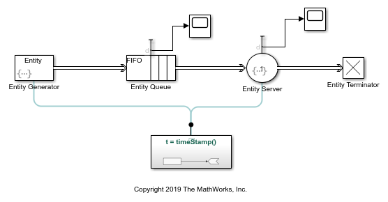
To open the model, use this code:
open_system('TimeStampEntitiesUsingSimulinkFunctionModel');
In this model, the entity intergeneration intervals are generated from a uniform distribution on the open interval (0,1). The entities have four attributes and all attributes have an initial value of 0:
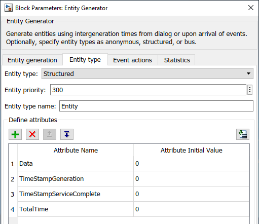
Datarepresents the data the entities carry.
TimeStampGenerationstores entity generation time.
TimeStampServiceCompletestores entity service completion time.
TotalTimeis the time between an entity's generation and service.
In the Simulink Function block, the Digital Clock block timestamps the entity generation time.
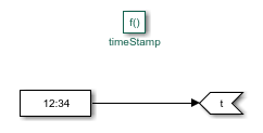
You can timestamp when the entity is generated by calling the timeStamp() function in the Simulink Function from the Entity Generator block.
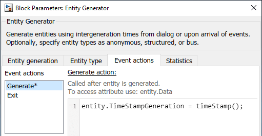
To call the function, in the Entity Generator block, in the Event actions tab, in the Generate field, use this code:
entity.TimeStampGeneration = timeStamp();
The code calls the timeStamp() function and assigns the value from the Digital Clock block to the TimeStampGeneration attribute when the entity is generated.
Similarly, to timestamp service completion and calculate the time difference between entity generation and service, open the Entity Server block, and in the Event actions tab, click the Service complete. Enter this code.
% Stamp the service completion by calling the |timeStamp()|
% function.
entity.TimeStampServiceComplete = timeStamp();
% Calculate the difference between generation and service
% completion time.
entity.TotalTime = entity.TimeStampServiceComplete - entity.TimeStampGeneration;
% Display the entity attribute for the time difference.
disp(entity.TotalTime);
The service completion time, which is acquired by calling timeStamp(), is assigned to the entity.TimeStampServiceComplete attribute. Then the duration between the entity's generation and service completion is calculated and assigned to entity.TotalTime. The code displays entity.TotalTime values for each entity in the Diagnostic Viewer.
Simulate the model. In the Diagnostic Viewer, you can observe the entity.TotalTime values for 10 entities. The duration between entity generation and service increases because entities wait in the Entity Queue block for their turn of service.

Increase the simulation time to 1000 and observe that entity.TotalTime converges to approximately 26.
Pass TotalTime Attribute to a Simulink Component
Suppose that you want to pass entity.TotalTime values to a Simulink® component. This model shows how to pass the attribute value to a Simulink Function block when an entity arrives at the Entity Terminator block.
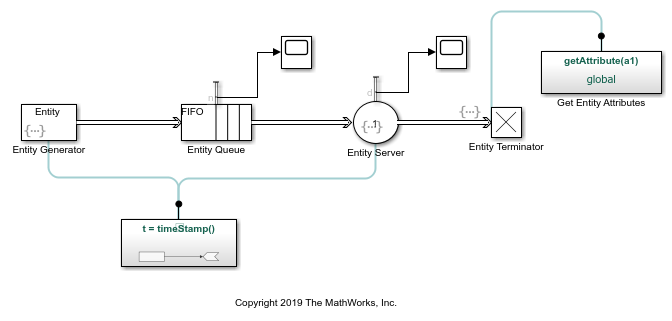
To open this model, use this code:
open_system('GetEntityAttributesSimulinkFunctionModel');
To achieve this behavior, open the Entity Terminator block, in the Event actions tab, click Entry and call the getAttribute(entity.TotalTime) function.
The Get Entity Attributes block takes entity.Totaltime as the input argument and uses a Gain block to amplify its values by multiplying them by 2.
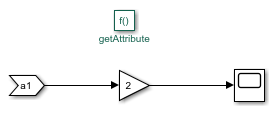
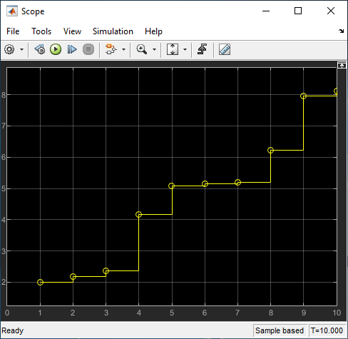
Simulate the model. Observe the Scope block that shows the amplified attribute values.
Import Data from a Spreadsheet to Specify Entity Intergeneration Times
Suppose that you want to incorporate data from a spreadsheet to your simulation. Using a spreadsheet, you can specify various parameters in your model, such as entity intergeneration time, entity attributes, or service time.
This example model shows how to import data from a spreadsheet to a SimEvents® model and use data to specify entity intergeneration times.
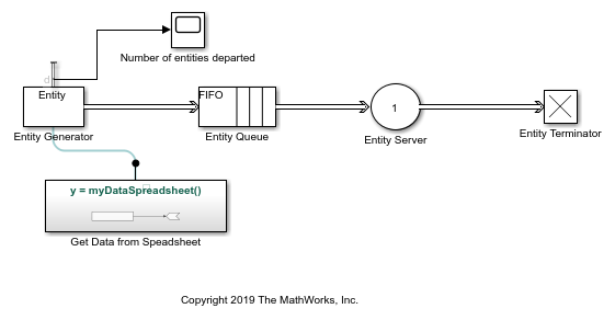
To open this model, use this code:
open_system('ImportDataSimEventsModel');
In the model, a From Spreadsheet block is inside the Simulink Function block and acquires values from the interGenerationTimes.xlsx spreadsheet. The spreadsheet has five values — 1, 2, 3, 4, and 5 — to be used as entity intergeneration times.
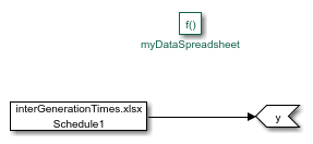
To call the myDataSpreadsheet() function, in the Entity Generator block, in the Intergeneration time action field, use this code:
dt = myDataSpreadsheet();
dt is the variable that specifies the intergeneration times for entities. The code assigns dt values by calling the Simulink function myDataSpreadsheet(), which acquires values from the spreadsheet.
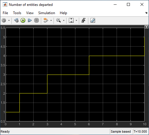
Simulate the model. Observe the Scope block that displays when entities are generated and depart the block. The intervals between entity generation are the same as the data from the spreadsheet.
Pass Entity Attributes Between Different Entity Types
In SimEvents, you can create a model that has different entity types and pass the attributes between entities using a Simulink Function block.
To open this model, use this code:
open_system('AssignEntityAttributeSimulinkFunctionModel');
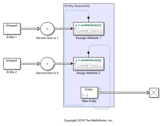
In the model, two Entity Generator blocks generate entities. Entity 1 generates entities with a constant value of 2 and are serviced for 1 simulation time. After the service is complete, the entities arrive at the Simulink Function block labeled Assign Attribute 1.
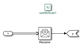
In Assign Attribute 1, entities are received by a Receive block with an internal queue of size 16. The Receive block converts the entity data to signal values.
Similarly, Entity 2 generates entities that carry data of value 2 and are serviced for 5 simulation time. After the service is complete, entities arrive at Assign Attribute 2.
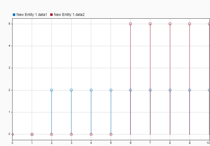
The entity data is passed to another Entity Generator block labeled New Entity. The New Entity block generates entities carrying two attributes, data1 and data2, whose values are acquired by calling setAttribute1() and setAttribute2(), respectively.
entity.data1 = setAttribute1();
entity.data2 = setAttribute2();
Simulate the model and open the Data Inspector. Observe that the values of data1 and data2 values of the new entity are 0 until simulation time 2. This is because entities are serviced and there is no attribute pass between the entities. At time 2, data1 is 2, which is the value that is passed by setAttribute1(). At time 6, data2 starts to acquire values from setAttribute2(). This delay is due to the difference between the service times of the entities.
Create a Notification Event for Routing
This model shows how to use a Simulink Function block to create an event to notify a routing block when an entity's processing is complete.
To open this model, use this code:
open_system('NotifyEventSimulinkFunctionCallModel');
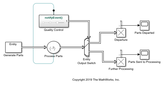
In the model, an Entity Generator block generates entities that represent parts in a facility. The entities are then processed by an Entity Server block. If a part passes quality control, the Entity Output Switch block routes the parts to Departure. Otherwise, the parts are sent to Further Processing.
To create a notification event after an entity is processed, in the Entity Server block, in the Event actions tab, in the Service complete action field, call the notifyEvent() function.
In the Quality Control block, a Sine Wave block is used to generate a signal. A Round block is used to round the signal values to the nearest integer less than or equal to that value. The output signal from the Round block takes the value 1 or 2. The signal is converted to a message by the Set Event Time block.
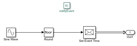
The message data value from the Quality Control block specifies which output port is selected when entities depart the Entity Output Switch block. If the message carries value 1, output port 1 is selected for entity departure. If the message carries value 2, output 2 is selected for entity departure.
Simulate the model and observe the Scope block labeled Parts Departed. Four parts depart the facility.
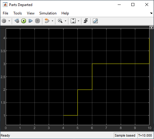
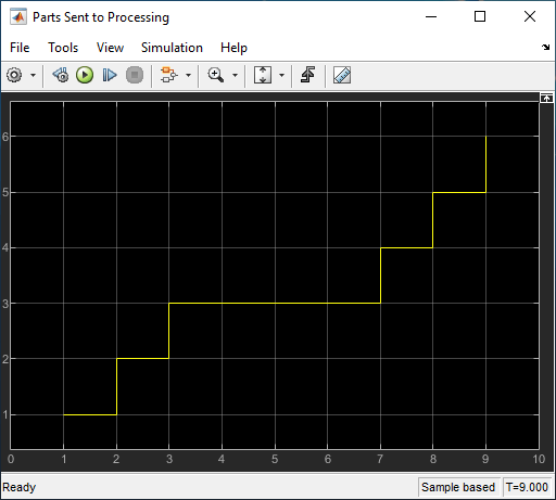
Observe the Scope block labeled Parts Sent to Processing, which shows that six parts are sent to further processing.
See Also
Gain | Entity Generator | Entity Queue | Entity Server | Entity Terminator | Bias | Simulink Function