Model Basic Queuing Systems
This example shows how to model basic queueing systems in a discrete-event simulation using the Entity Queue and Entity Server blocks.
The Entity Queue block stores entities for a length of time that cannot be determined in advance. An everyday example of a queue is people waiting in line for a store register. A shopper cannot determine in advance how long they must wait to complete their purchase. You can use Entity Queue in different applications such as airplanes waiting to access a runway or messages waiting to be transmitted. The Entity Queue block has storage capacity, entity sorting policy, and entity overwriting policy. Based on these parameters, the block attempts to output entities depending on whether the downstream block accepts new entities.
The Entity Server block stores entities for a length of time, called the service time, then attempts to send the entity depending on whether the downstream block accepts new entities. During the service period, the block is serving the entity that it stores. An everyday example of a server is a person (such as a bank teller or a retail cashier) with whom you perform a transaction with a projected duration.
This example presents basic queuing models that show how to:
Model FIFO queue, LIFO queue, and Priority queue.
Specify entity overwriting policies when the queue reaches capacity.
Customize and vary entity service times.
Assign and change entity attributes based on events.
Understand queue length statistics during simulation.
Sort Entities Using the Entity Queue Block
This model shows how to sort entities by changing the queue sorting policy. The Entity Queue block supports three message sorting policies:
Last-in-first-out (LIFO) — The newest entity in the storage departs first.
First-in-first-out (FIFO) — The oldest entity in the storage departs first.
Priority — Entities are sorted based on their priority. You can only use the priority queue when the Overwrite the oldest element if queue is full check box is cleared.
The model below shows four different entity sorting behaviors: FIFO, LIFO, Priority in ascending order, and Priority in descending order.
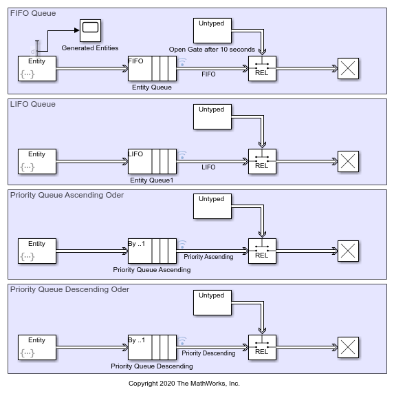
Four identical Entity Generator blocks generate 10 entities each. Each block uses a repeating sequence pattern for entity intergeneration time dt.
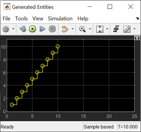
After generating 10 entities, the intergeneration time dt is set to infinity to stop generating entities. In the Entity Generator block, in the Intergeneration time action field, this code is used.
persistent SEQ;
persistent idx;
if isempty(SEQ)
    % Generate 10 entities with 1 second intervals.
    SEQ = [1 1 1 1 1 1 1 1 1 1];
    idx = 1;
end
if idx > numel(SEQ)
    % Stop entity generation after generating 10 entities.
    dt = inf;
else
    dt = SEQ(idx);
end
The block generates an entity and it specifies the attribute Attribute1 on each entity. You can use attributes to represent features or properties of entities. In this example, the first entity carries a value of 1, and each generated entity's attribute value increases by 1. To achieve this behavior, in the Entity Generator block, in the Event actions tab, in the Generate action field, this code is used.
% Pattern: Repeating Sequence
persistent SEQ1;
persistent idx1;
if isempty(SEQ1)
    SEQ1 = [1 2 3 4 5 6 7 8 9 10];
    idx1 = 1;
end
if idx1 <= numel(SEQ1)
    entity.Attribute1 = SEQ1(idx1);
end
idx1 = idx1 + 1;
The generated entities are forwarded to the four Entity Queue blocks. In order to show the sorting behavior, the Entity Queue blocks are connected to four identical Entity Gate blocks configured as release gates. A release gate allows one entity to pass when it receives an entity carrying a positive (greater than 0) value from its control port. The gates block entities for the first 10 seconds and store them in the queue. After the first 10 seconds, the gates allow one entity to pass per second based on the sorting policy.
Simulate the model. Open the Simulation Data Inspector and observe that the entities departing from each Entity Queue block are sorted based on the queue sorting policy.
The first plot shows entities departing from the queue with a FIFO policy. The first entity with
Attributevalue1, departs from the queue when the gate opens at time11. Subsequent entities depart the queue in the same order of their generation, with increasing attribute value.
The second plot shows entities departing from the queue with a LIFO policy. This policy reverses the entity departure sequence starting with the entity carrying the largest attribute value.
The third plot shows entities departing from a priority queue that sorts entities based on their attributes in ascending order instead of their order of entry to the queue. The entity carrying the smallest attribute value departs first. Subsequent entities follow the same policy.
The fourth plot shows the entities departing from a priority queue that sorts entities based on their attributes in descending order. The entity with the largest attribute value departs first and the rest of the entities follow the same policy.

Queue Entity Overwriting Policies
You can specify what Entity Queue block does when the block reaches its capacity by setting the entity overwriting policy. Specify the policy by selecting or clearing the Overwrite the oldest element if queue is full check box.
If the Overwrite the oldest element if queue is full check box is cleared, the block does not accept new entities when the queue is full. This is a blocking queue behavior.
If the Overwrite the oldest element if queue is full check box is selected, the block is set to always accept an incoming entity by overwriting the oldest entity in the storage. The block overwrites the oldest entity, but the entity departing the block is determined by the queue sorting policy.
In this model, two identical Entity Generator blocks generate entities every 1 second. The entities are forwarded to two Entity Queue blocks each with a capacity of 10 and a FIFO entity sorting policy. However, the Blocking Queue is configured to not accept new entities when its queue is full, while the Overwriting Queue is configured to overwrite the oldest entity when its queue is full. Blocking Queue and Overwriting Queue are connected to two identical Entity Server blocks, each with a service time value of 25 seconds. The entity generation rate of the Entity Generator block is much higher than the service rate of Entity Server block. This difference causes entities to accumulate in the Entity Queue block.

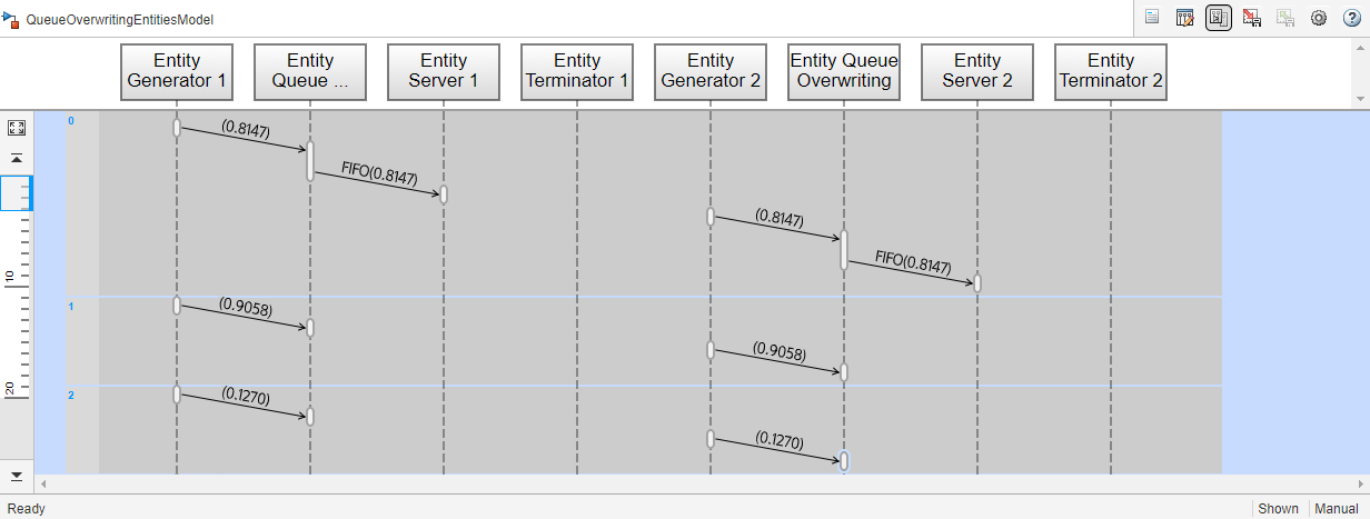
Simulate the model and open the Sequence Viewer block. Observe that the Entity Generator 1 and Entity Generator 2 blocks initially generate entities with data values of 0.8147, and the entities are forwarded to Entity Server 1 and Entity Server 2. Both Entity Generator blocks generate a second set of entities with data values of 0.9058, which are stored in the Blocking Queue and Overwriting Queue because both Entity Server blocks are full. The rest of the generated entities are also stored in the Entity Queue blocks.
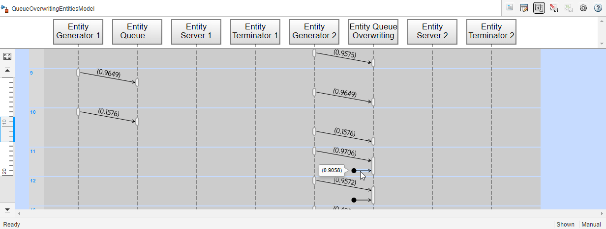
Observe that Entity Queue 1 block stops accepting new entities to its storage the time 11. However, Entity Queue 2 allows the new entity with attribute 0.9706 to storage and overwrites the oldest existing entity, which has a data value of 0.9058.
Customize Entity Service Time
In a basic queuing system, you can use an Entity Server block to model delays based on the processes in your system. You can determine the source that specifies the delay by changing the Service time source parameter of the Entity Server block.
This example shows four different sources you can use based on your application:
Dialog— You can define a constant service time value. In the first modeling pattern, entities are delayed for2seconds. The block then attempts to forward entities to the next block.Signal port— An incoming Simulink® signal determines the service time. In the second modeling pattern, the block uses ramp signal values as the service time source.Attribute— A specified entity attribute value determines the service time. In the third modeling pattern, each entity carriesAttribute1with value4which is the service time source.
MATLAB action— You can enter MATLAB™ code in the Service time action field and assign the variable todt, which is the parameter the model uses as service time. In the fourth modeling pattern, the random service timedt = rand(1,1);is used, and the code sets a random service time value that is uniformly distributed between0and1.
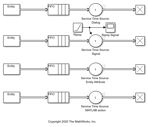
Simulate the Model and Review Results
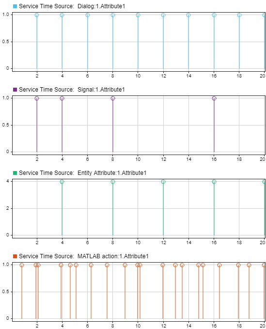
Simulate the model and observe the Simulation Data Inspector, which displays entities forwarded by the Entity Server block.
Build a Simple Queuing System to Change Entity Attributes
You can attach attributes to entities to represent their features. In a queueing system, you can use actions as responses to events and change entity attributes. For instance, you can change the value of an entity attribute when the entity enters and exits the Entity Queue block. In the Entity Queue block, in the Event actions tab, you can see the set of events for which you can create actions.
Suppose you want to model a customer service system in a bank branch. The branch has two bank tellers, each assigned a particular transaction type. Customers arrive at the branch. They pick a number for their transaction and they are directed to the correct bank teller. Customers leave the branch after the transaction is complete.
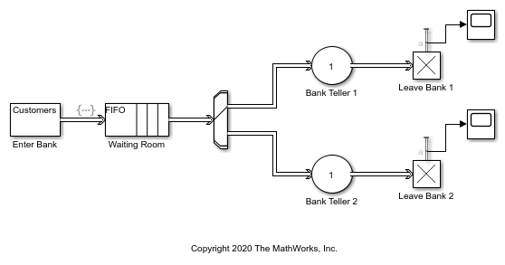
In this example, customer arrivals are modeled by an Entity Generator block. The customers are assumed to arrive with constant interarrival times, and the Period is 1. Each generated entity is attached an attribute TransactionType to represent the customer requests. The TransactionType|is initialized as |0 because the transaction is unknown before the customers enter the branch.
The waiting room is represented by an Entity Queue block. When a customer enters the waiting room, they are given a number for the corresponding bank teller. This action is represented by changing the entity attributes in the event actions of the Entity Queue block. Below is the action invoked by the entity entry event to the Entity Queue block.

Analyze Queue Length Using Statistics and Logical Queues
You can use queue statistics to analyze and understand the behavior of a queue in your simulation. Specifically, you can measure:
The number of entities departed from a queue to a downstream block.
The number of entities at a specific simulation time.
The average wait of the entities in the queue before departing the block.
The average queue length or number of entities extracted from the queue by the Entity Find block.
Understanding these statistics can give insight about your model's behavior. For more information about queue statistics, see Interpret SimEvents Models Using Statistical Analysis.
This example presents two different methods for visualizing and understanding queue length.
To determine whether a queue is storing any entities, you can output the statistics that correspond to the number of entities stored in a block.
To output statistics follow these simple steps.
Enable the n output signal from the queue block. In the block dialog box, on the Statistics tab, select the Number of entities in block, n check box.
From the Sinks library in the Simulink® library set, insert a Scope block into the model. Connect the n output port of the queue block to the input port of the Scope block.
The scope shows if the queue is empty.
For more information about visualizing queue statistics, see Explore Statistics and Visualize Simulation Results.
Partition a Queue to Understand Queue Length
You can partition a queue to understand more details about the queue length and behavior during simulation.
Suppose that you want to determine what proportion of the time the queue length exceeds 10 for a queue with a capacity of 100. You can investigate this by using a pair of queues connected in series. The queues have lengths of 90 and 10. Together they represent a queue with a capacity of 100.
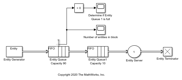
Partitioning the original queue into two smaller queues allows you to gather statistics related to one of the smaller queues. For example, you can view the queue length statistic for the Entity Queue block of with a capacity of 90. If there are entities accumulated in the queue with a capacity of 90, in means that the queue with a capacity of 10 is full. Thus, determining the proportion of the time that the queue with a capacity of 100 has minimum 10 entities is equivalent to determining the proportion of time the queue length of the queue with a capacity of 90 is greater than 0.
Simulate the model. Observe that the Entity Queue Capacity 90 block outputs the Number of entities in block, n. Observe that in certain time intervals entities are stored in the block, which indicates that the queue with a capacity of 10 is full.
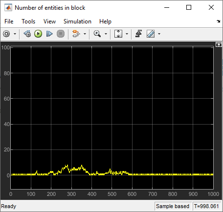
To visualize the proportion of time that the queue with a capacity of 10 is full, the statistic signal is further processed and compared to zero.
