Simulate High Frequency Components
This example shows how to use RF Blockset™ circuit envelope simulation to simulate high frequency components while reducing simulation time.
Simulate Passband Signal in Simulink Software
The model, ex_simrf_tut_passband_model, shows how to modulate a real passband signal with in-phase and quadrature components.
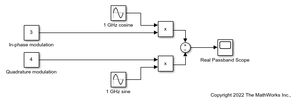
The system specifies a real passband signal x(t) according to the formula

where:
I(t) is the in-phase part of the modulating signal and it is set to
3. This is modeled by the Constant block labeled In-phase modulation.Q(t) is the quadrature part of the modulating and it is set to
4. This is modeled by the Constant block labeled Quadrature modulation.fc is the carrier frequency and it is set to
1GHz.
Running the model produces the following output on the scope.
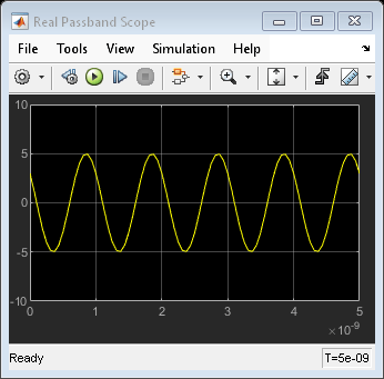
The output signal at the Real Passband Scope has a magnitude of 5 and a phase shift of atan2d(3,-4) or about 143 degrees.
In the Configuration block, the Fixed-step size (fundamental sample time) parameter has been set to 1/16*1e-9. This value is on the order of the wavelength of the carrier. The simulation takes a total of 81 samples – 16 per cycle.
Compare Passband and Baseband Signals in RF Blockset Software
The model, ex_simrf_tut_compare_model, shows how to compare passband and baseband signals. This section builds on the results of the previous section, Simulate a Passband Signal in Simulink Software.
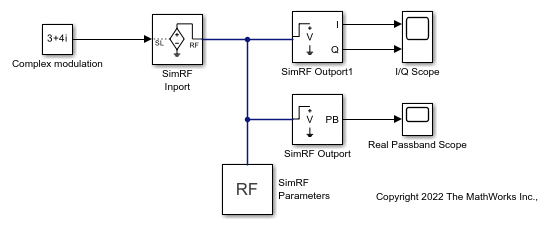
The system simulates a real passband signal as the real part of a complex passband signal according to the formula
![$$x(t) = {\mathop{\rm Re}\nolimits} [(I(t) + jQ(t)){e^{j2\pi {f_c}t}}] = I(t)\cos (2\pi {f_c}t) - Q(t)\sin (2\pi {f_c}t)$$](../../examples/simrf/win64/SimulateHighFrequencyComponentsExample_eq11976656997229644883.png)
where:
I(t) + jQ(t) is the complex-valued modulation, equal to 3 + 4j.
fc is the angular frequency, equal to 1 GHz.
Contrary to the Simulink® passband implementation in the previous section, the complex baseband signal driving the RF Blockset system does not include the carrier. Instead, the RF Blockset environment handles the carrier analytically. The carrier appears in four different blocks in the RF Blockset environment:
In the Inport block, the Carrier frequencies parameter defines the carrier frequencies of the modulations entering from outside the RF Blockset environment. In this example, there is only one input signal, and only one carrier (1 GHz, specified as 1e9 Hz).
In the Outport block, the Carrier frequencies parameter specifies the signal on the 1e9 Hz carrier (1 GHz) as Simulink signals. These signals appear at the I and Q ports. The Output parameter is set to Real Passband, so this signal represents a real passband signal on the 1-GHz carrier.
In the block labeled RF Blockset Outport1 block, also an Outport block, the Carrier frequencies parameter specifies the signal outputted on the 1e9 Hz carrier (1 GHz) as Simulink signals. These signals appear at the I and Q ports. The Output parameter is set to In-phase and Quadrature Baseband, so these signals represent the in-phase and quadrature modulations of the signal on the 1-GHz carrier.
In the Configuration block, the Carrier frequencies parameter specifies all of the carriers to be modeled in the RF Blockset circuit envelope simulation environment. In this example, only one carrier is specified. For more options, refer to Configuration block.
Running the model produces the following output on the scopes.
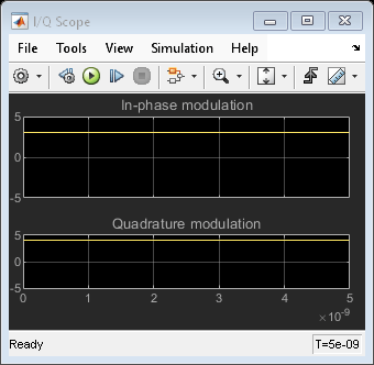

The Real Passband Scope displays the same output as the example in the previous section, Simulate a Passband Signal in Simulink Software. The signal has a magnitude of 5 and a phase shift consistent with the specified in-phase and quadrature amplitudes.
The 1-GHz carrier itself does not appear in the output. The results correspond to the real and imaginary parts of the Complex modulation at the input of the system. They also correspond to the In-phase modulation and Quadrature modulation blocks in Simulate a Passband Signal in Simulink Software.
In the Configuration Parameters dialog box, the Fixed-step size (fundamental sample time) parameter has been set to 1/16*1e-9. This value is on the order of the wavelength of the carrier. The simulation takes a total of 81 samples – 16 per cycle.
Simulate Envelope of Baseband Signal
The model, ex_simrf_tut_envelope_model, shows how to simulate the envelope of a sine wave using RF Blockset blocks. This section builds on the results of the previous section, Compare Passband and Baseband Signals in RF Blockset Software.
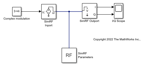
The system is almost identical to the system in the previous section, except:
The model contains only one RF Blockset Outport block and only one scope. The RF Blockset environment outputs in-phase and quadrature modulations of the 1-GHz signal. In the RF Blockset Outport block, the Output parameter is set to In-phase and quadrature baseband. Since the system is not configured to output a real passband signal, the carrier is not simulated.
In the Configuration Parameters dialog box, the Fixed-step size (fundamental sample time) parameter is greater. Its value is
5e-9instead of1/16*1e-9.
Running the model produces the following output at the scope.

The I/Q Scope displays the in-phase and quadrature baseband components of the 1-GHz signal. The 1-GHz carrier itself does not appear in the output. The results correspond to the real and imaginary parts of the Complex modulation at the input of the system.
In contrast to the models in the previous two sections, Simulink works differently in this model. Because the modulating signals are constant in this example, only two sample points are needed. To simulate a time-varying modulating signal, Simulink can use a fixed time step on the order of the reciprocal of its bandwidth.
The model uses a value of 5e-9 for the Fixed-step size (fundamental sample time) parameter. This value equals the Stop time because, in this case, the modulating signals are constant. Compared to the preceding examples, which use a sample time of 1/16*1e-9, this model simulates accurately with a time step 80 times larger. This step size results in a reduction of total sample time by a factor of 80, excluding the initial time step at time 0.
See Also
Inport | Outport | Configuration