Model RF Mixer
This example shows how to
Use a Sinusoid block to model the envelope of an amplitude-modulated (AM) waveform.
Use a Continuous Wave block to model the constant envelope of an ideal local oscillator (LO).
Use a Mixer block to downconvert the AM waveform to an intermediate frequency (IF).

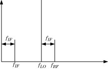
The preceding figure illustrates frequency conversion. A signal modulated on the carrier fRF mixes with a local oscillator at fLO. The operation downconverts fRF to fIF = fRF – fLO. The upper mixing product fRF + fLO is not modeled.
Build RF System
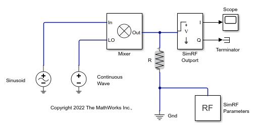
This model specifies an AM waveform at the input port of the mixer, an LO at the LO port of the mixer, and a 50 ohms termination at the output of a mixer.
To build this model, open the RF Blockset library by typing simrfV2libs in the MATLAB® Command Window.
Double-click the block labeled Circuit Envelope to open the Circuit Envelope library.
From the Elements, Sources, and Utilities sublibraries, add the following blocks to your model.
From the Elements library, add a Resistor, a Mixer, and a Ground blocks.
From the Sources library, add a Continuous Wave and a Sinusoid block.
From the Utilities library, add a Configuration block.
Connect the blocks in the same configuration as shown in this image.

Define Model Variables
For models with blocks that share parameter values, specifying parameters values using variables saves time and effort.
Simulink® models run MATLAB code stored in the initialization function ( InitFcn ) each time the model starts. The MATLAB code runs in the base workspace. If the initialization function stores variables in the MATLAB workspace, the variables are overwritten every time the model executes the initialization function.
In Simulink editor, click Modeling. In the toolstrip, in SETUP> Model Settings, click Model Properties .
In the Callbacks tab, within the Model callbacks pane, select the InitFcn node.
In the Model initialization function pane, enter the following MATLAB code:
modulationAmplitude = 1; modulationFrequency = 5e5; LOAmplitude = 1; LOFrequency = .95e9; RFCarrier = 1e9;
Specify Block Parameters for RF Simulation
In this section you will learn how to:
Configure the RF Blockset(M) environment for multi-frequency circuit envelope simulation by specifying the Simulation frequencies parameter in the Configuration block dialog box
Specify the attributes of the waveforms *Configure global simulation settings
Using block dialog boxes to specify the parameters for simulation:
In Simulink editor, click Simulation in the PREPARE , click Model Settings in Configuration and Simulation. Specify the following parameters:
Set Stop time to
1e-5. You can also set the stop time directly on the Simulink canvas.Set Solver to
ode23t (mod. stiff/Trapezoidal). The RF Blockset environment does not use theode23tsolver. However, since oscillating signals can be stiff, the solver is a good choice for the Simulink environment when using RF Blockset blocks.
Double-click the Sinusoid block to open the Sinusoid Block Parameters dialog box. Specify the following parameters:
Set Sinusoidal amplitude in-phase to
modulationAmplitude.Set Sinusoidal modulation frequency to
modulationFrequency.Set Carrier frequencies to
RFCarrier.
Double-click the Continuous Wave block to open the block dialog box. Specify the following parameters:
Set Constant in-phase value to
LOAmplitude.Set Carrier frequencies to
LOFrequency.
Double-click the Configuration block to open the block dialog box. Set Step size to 1e-7.
Probe Circuit Envelopes Waveforms
At the output of the mixer:
From the RF Blockset Utilities library, drag and drop an Outport block onto your model. In the block dialog:
Set Output to
In-phase and quadrature.Set Carrier frequencies to
RFCarrier – LOFrequency.
From the Simulink Commonly Used Blocks library, drag and drop a Scope block and a Terminator block onto your model.
This configuration uses a RF Blockset Outport block as a voltage sensor at the output port of the mixer. The Simulink signal at the outport is the envelope of the carrier or carriers specified in the block. A scope attached to the outport plots the envelope. The Output parameter controls how signals are presented at the output ports. To change the appearance of the block, follow one of the workflows in the Specify Block Parameters for RF Simulation section of this tutorial.
Observe Downconverted Envelope Signal at Output Port
Click Run to run the model. To view the results of the simulation, double-click the scope, and click the Autoscale button.
The Sinusoid specifies a 1-V amplitude for the modulation on fRF, which the mixer downconverts to fIF. The RF Blockset Outport block probes the intermediate frequency and recovers the 1-V modulation amplitude. This value agrees with a specified conversion gain of 0 dB in the mixer.
