Build RF System Using Baluns
R2026bThis example shows how baluns enable differential signaling in a RF transmitter chain.
System Architecture
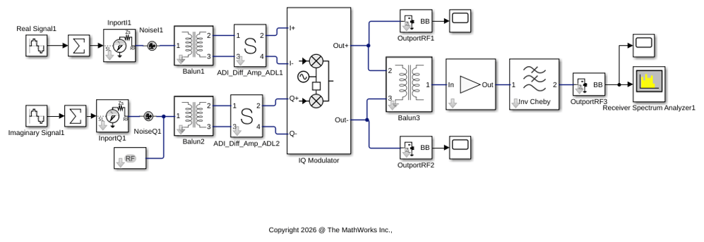
The model implements a complete IQ upconversion transmitter where baluns serve three distinct roles:
Input baluns (Balun1, Balun2) convert single-ended I and Q baseband signals into differential pairs for the differential amplifiers.
Output balun (Balun3) recombines the differential RF output from the IQ modulator back into a single-ended signal for the driver amplifier.
The model allows observation of RF impairments such as:
Image signals due to I/Q gain mismatch.
Intermodulation distortion (IMD) products.
Output third-order intercept point (OIP3).
Baluns in Signal Chain Architecture
Each input balun converts the single-ended baseband signal into a differential pair. Balun1 handles the I-path and Balun2 handles the Q-path. These baluns split the input signal into two equal-amplitude, 180-degree phase-shifted outputs that drive the differential amplifiers.
The output balun recombines the differential RF output from the IQ modulator into a single-ended signal. The output balun transforms the differential output impedance to 50 ohms for the subsequent single-ended driver amplifier stage.
The IQ modulator accepts differential I and Q inputs and produces a differential RF output. The input voltages are converted to currents and translated to the LO frequency using double-balanced up-conversion mixers.
Simulate the RF Transmitter Chain
Run the simulation to observe the IQ modulator output spectrum. The simulation time is set to 0.11 ms, providing sufficient cycles for the 10 MHz and 15 MHz baseband tones to produce a clear spectrum.
ans =

     []


ans =

     []


ans =

     []
Analyze the Results
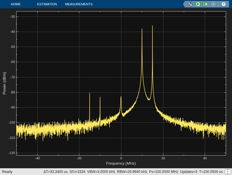
After simulation, examine the Spectrum Analyzer (connected to OutportRF3) to observe:
Desired signals at 2 GHz + 10 MHz = 2.010 GHz and 2 GHz + 15 MHz = 2.015 GHz (upper sideband).
Image signals at 2 GHz - 10 MHz = 1.990 GHz and 2 GHz - 15 MHz = 1.985 GHz (lower sideband), caused by the 0.1 dB I/Q gain mismatch. These are suppressed relative to the desired signals by approximately 40 dB for a 0.1 dB mismatch.
The Scope blocks ( Scope1 , Scope2 ) show the time-domain differential outputs of the IQ modulator, confirming equal amplitude and 180-degree phase relationship. Scope3 shows the final filtered RF output envelope.

