Design Receiver with ADC
Most RF receivers in modern communications or radar systems feed signals to an analog-to-digital converter (ADC). Due to their finite resolution, ADCs introduce quantization error into the system. The resolution of the ADC is determined by the number of bits and the full-scale (FS) range of the ADC.
The preceding figure illustrates an RF signal that falls within the dynamic range (DR) of an ADC. The input signal and noise at the carrier fRF has high signal-to-noise ratio (SNR). The received signal at fIF has reduced SNR due to system noise figure. However, if the quantization error is near or above the receiver noise, system performance degrades.

To ensure that the ADC contributes no more than 0.1 dB of noise to the signal at fIF , the quantization noise floor must be 16 dB lower than the receiver noise. This condition can be met by:
Reducing the full-scale (FS) range or increasing the resolution of the ADC, which lowers the quantization noise floor.
Increasing the gain of the RF receiver, which raises the receiver noise floor.
Overcome Quantization Error of an ADC
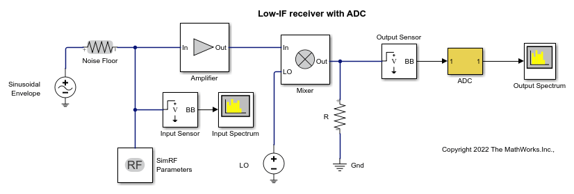
The model ex_simrf_adc_rx simulates a low IF receiver with an ADC. This model is based on low IF receiver design from the Model System Noise Figure. At the output of the RF system, the ADC subsystem models an ADC with an FS range of sqrt(100e-3) V and a resolution of 16 bits.
open_system("ex_simrf_adc_rx")

The power of a voltage signal at the full-scale range of the ADC in dBm is
P_vs = 10*log10(sqrt(100^-3))+30 = 0
View Simulation Output
The power levels shown in the figures represent the power spectral density (PSD) of the signals in dBm/Hz.
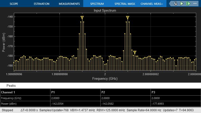
The Spectrum Analyzer Block shows the power spectrum of the two-tone signal and noise at the input of the receiver-ADC system. The measured power of each tone of -142 dBm is consistent with the expected power level of a 0.1 uV signal. The power level of the noise is consistent with a -174 dBm/Hz noise floor. The output spectrum plot shows power spectrum of the output signal.
sim("ex_simrf_adc_rx")


The quantization error exceeds the receiver noise.
Measure Quantization Noise Floor
To calculate the quantization noise floor (QNF_ADC) of the ADC, subtract the dynamic range from the full-scale power, which is 0 dBm. QNF_ADC is calculated using this equation:
QNF_ADC = 6.02*N_bits + 10*log10(deltaf) + 1.76 = 116.1 dBm/Hz
where
N_bits is the resolution. The ADC in this example uses 16 bits.
deltaf is the bandwidth of the FFT, which is 64 in this example. Oversampling in an ADC yields lower quantization noise.
The value 1.76 is a correction factor for a pure sinusoidal input.
Therefore, the quantization noise floor is -116 dBm/Hz, in agreement with the measured output levels.
Improving Receiver-ADC Performance
Increasing the gain in the mixer raises the receiver noise without increasing the noise figure. Calculate the mixer gain required to achieve a 16-dB margin between the quantization noise floor and the receiver noise:
G_mixer = (QNF_ADC+16) - (-174+G_sys+NF_sys) = (-116.1+16) - (-174+40+10) = 23.9 dB
To simulate a receiver that clears the quantization noise floor: set the Available power gain parameter of the mixer to 23.9 and click Run.
sim("ex_simrf_adc_rx_mixer")

The figure shows that the receiver noise is 16 dB above the quantization noise floor.