Measuring Image Rejection Ratio in Receivers
This example shows how to use the RF Blockset™ Circuit Envelope library to calculate the image rejection ratio (IRR) for high-side-injection in Weaver and Hartley receivers. The Weaver receiver shows the effect of phase offset on IRR, and the Hartley receiver shows a similar effect for resistor variation.
model1 = 'simrfV2_hartley';
open_system(model1);

System Architecture
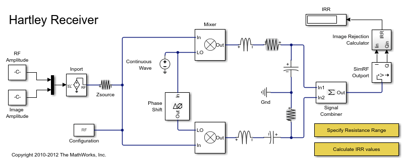
The RF system consists of:
An Inport block that assigns multiplexed outputs of the RF and Image, by using Simulink® Constant blocks, to the carriers
fc_RFandfc_IMrespectively. Real and imaginary values of the Constant blocks are matched to in-phase and quadrature carrier components.First stage mixers that mix the input signal with a local oscillator modeled by a Continuous Wave block with frequency
fc_LO. The LO frequency is the average of the RF and image frequencies, so both signals are mixed down to the same frequency,fc_IF. The LO phase is shifted 90 degrees in one mixer relative to the other.The second stage of the Hartley uses a frequency independent RC-CR network to produce an additional 90 degree phase shift between the two signal paths, while the Weaver employs two additional mixers for channel selection.
A Signal Combiner block that sums the voltage signals at its two inputs to yield the RF signal. If the Signal Combiner block is used to perform subtraction, the image can be obtained instead of the RF signal at its output. For low-side-injection, the Signal Combiner block needs to perform subtraction.
The values of the in-phase and quadrature components of the RF and image signals are chosen to reduce the number of IRR calculations and facilitate reuse of the Image Rejection Calculator.
Simulating the Hartley Receiver
Type
open_system('simrfV2_hartley')at the Command Window prompt.Double-click 'Specify Resistance Range' and specify a set of resistance values for the highlighted resistor.
Double-click 'Calculate IRR values' to execute a script,
simrfV2_hartley_callback, that simulates the model once for each specified resistance value and generates a plot.
The sensitivity of the architecture to the component variation is shown by simulating the system multiple times, varying the resistance of the highlighted Resistor block at each iteration. When the highlighted resistor has a resistance of 1 Ohm, the images sum to zero in the Signal Combiner block and the IRR is minus infinity.
evalc('simrfV2_hartley_callback');

bdclose(model1);
model2 = 'simrfV2_weaver';
open_system(model2);

Simulating the Weaver Receiver
Type
open_system('simrfV2_weaver')at the Command Window prompt.Double-click 'Specify Phase Offset Values' and specify a set of phase offset values.
Double-click 'Calculate IRR values' to execute a script,
simrfV2_weaver_callback, that simulates the model once for each specified offset and generates a plot.
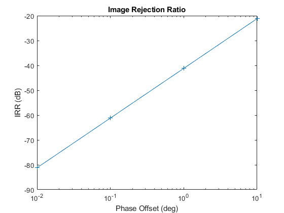
The sensitivity of the architecture to LO phase offset is shown by simulating the system multiple times, varying the phase offset of the highlighted Phase Shift block at each iteration. When the phase offset of the highlighted Phase Shift block is zero, the images sum to zero in the Signal Combiner block and the IRR is minus infinity.
evalc('simrfV2_weaver_callback');

bdclose(model2)