Main Content

Charge Battery Module with Charger Block

Since R2024a

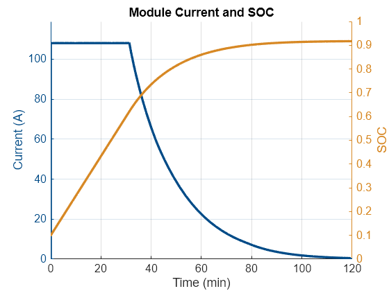
This example shows how to charge a battery module using a constant-current step followed by a constant-voltage step. This is a CC-CV profile. The battery simulation utilizes a Simscape™ Battery™ Charger block. At the start of the simulation, the battery module has a state of charge (SOC) of 10%. The Charger block performs a constant-current (CC) charging until it reaches the predefined module voltage limit of 4.1 V. The block then switches to a constant-voltage (CV) control step where the current gradually decreases until it reaches a threshold of 0.5 A, specified in the Current Threshold parameter. The charging procedure stops once the current reaches the designated threshold.

Model Overview

Open the controlledChargingSsc model.

modelname = "controlledChargingSsc";
open_system(modelname);
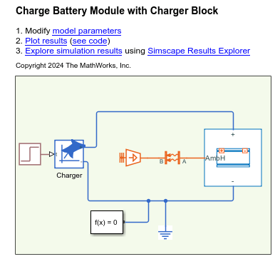
The model comprises a pre-generated Module block and a Charger block. The Module block represents a battery module with three parallel assemblies with a gap between each parallel assembly of 0.5 mm, a detailed model resolution, and an enabled ambient thermal path. Each parallel assembly comprises four single-stacked pouch cells. Each pouch cell measures 300 mm in length, 100 mm in height, and 10 mm in thickness. For more information on how to generate the Module block, open the controlledChargingSscCreateLib.mlx file.

Run the simulation.

ssc_cntrlChrgSsc = sim(modelname);

Simulation Results

This plot shows the current and SOC of the battery module during the simulation.

controlledChargingSscPlotSOC;

Figure controlledChargingSsc contains an axes object. The axes object with title Module Current and SOC, xlabel Time (min), ylabel SOC contains 2 objects of type line.

See Also

|

Related Topics