Model Heat Exchange Between Cells
You can use Simscape™ Battery™ to model direct cell-to-cell heat exchange. By modeling these interactions accurately and dynamically, you can design battery systems and battery management systems that maintain optimal operating temperatures, extend the lifespan of the battery, and reduce the risk of cell-to-cell thermal runaway propagation.
You can use these capabilities to simulate detailed thermal management strategies or thermal propagation scenarios where inter-cell heat transfer occurs faster than ambient or coolant rates. In battery system design, you can thermally isolate battery cells by using air gaps or polymer compounds. Alternatively, you can thermally link battery cells by using thermal interface materials and cell holders. This thermal design depends on the application and safety requirements. For example, you can link cylindrical cells by using potting compounds for mechanical rigidity, stability, and thermal isolation, or you can use other types of thermal interface materials. To meet different application requirements, you can also use dielectric fluids, other compounds, or forced air convection to heat or cool down cylindrical cells.
The thermal design significantly influences the performance and safety of the battery. During operation, the cells in your battery generate heat. To prevent overheating and failures, you must provide efficient heat dissipation from each cell to a coolant or to an ambient thermal sink. Although, good cell-to-cell heat exchange can be an advantage during normal operation because it helps maintain temperature uniformity, it increases the risk of failure propagation in the event of a thermal runaway.
Use the InterCellThermalPath and
InterCellRadiativeThermalPath properties of the battery objects to
customize the thermal behavior of your battery model. After you create the battery model, you
can define the thermal parameters for inter-cell heat exchange. You can find these parameters
from first principles calculations and detailed 3-D simulations.
To adjust your model to reflect real-world conditions more accurately, parameterize the thermal resistance. This process can involve complex calculations and simulations, but it is essential for achieving a high-fidelity model that predicts the thermal behavior of your battery system under various conditions.
When you set the InterCellThermalPath property of your battery object
to "on", the software adds a single thermal resistor between the
thermal node of each cell and the node of each neighboring adjacent cell. This thermal resistor
represents a linear conduction heat exchange mechanism between the cells.
You can set the InterCellRadiativeThermalPath property to
“on” to model radiation heat exchange.
Note
Setting the InterCellThermalPath or
InterCellRadiativeThermalPath properties in an object propagate their
value to all the subcomponent battery objects inside this object. If you do not set these
properties when you create a battery object, then the default
"off" value is propagated to all its subcomponent battery
objects.
For example, consider a scenario where you create a Module object and
you set the InterCellThermalPath property to
"on". You then create a ModuleAssembly object
from this Module object and you do not set the
InterCellThermalPath property. By default, the
"off" value of the InterCellThermalPath
property is propagated to all the subcomponent battery objects of the
ModuleAssembly object, replacing the value you previously set in the
Module object.
To model the inter-cell thermal path of your battery, set the
InterCellThermalPath or
InterCellRadiativeThermalPath property at the highest parent level or
the level at which you want to generate the battery library.
This topic shows you methods for modeling inter-cell thermal resistance for cylindrical cell and pouch cell batteries.
Model Inter-Cell Thermal Resistance for Cylindrical Cell Batteries
In cylindrical-cells batteries, you typically fill the inter-cell spacing with an adhesive, a potting compound, a cell holder, an air gap, or a combination of these materials. These batteries might also model serpentine cooling plates, dielectric fluids, or other types of heat dissipation mechanisms between the cells. However, this coolant thermal path is best modeled separately from the other mechanisms. To calculate the inter-cell thermal resistance, you must know the configuration and properties of your thermal management system.
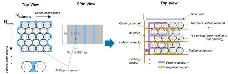
Calculate the inter-cell thermal resistance values by using the dimensions and material properties of the module constituents. This figure shows a typical layout for cylindrical cell batteries with hexagonal topology. Typical cell-to-cell thermal resistance values for batteries with cylindrical cells are in the range of 1 to 100 K/W.
The thermal resistance value typically captures the conduction resistance of the component between the cells. If you use a lumped thermal model to model the cell temperature, you can modify the inter-cell thermal resistance to include any additional desired intra-cell heat conduction mechanisms.
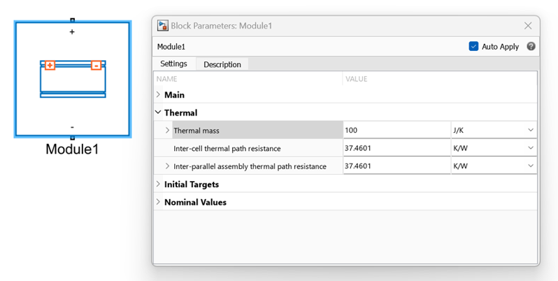
To specify the thermal resistance values of your battery objects, you must use them in
block diagrams. To use the battery objects in block diagrams, you must first convert them into
Simscape models. Generate the Simscape library containing the block associated to your object
by using the batteryBuilder function. Then, double-click the block and,
in the Thermal section of the block dialog box, specify the value of the
Inter-cell thermal path resistance parameter. Specify this value as a
scalar to apply the same value to all cell connections, or as a vector to apply specific
values to different cell connections.
To calculate the thermal resistance value, use this equation:
where:
Rinter-cell is the thermal resistance, in K/W.
d is the distance between heat transfer surfaces, in m.
A is the area of heat transfer, in m2.
k is the thermal conductivity, in W/(m*K).
This figure shows the configuration between two adjacent cylindrical cells. The distance and area between the neighboring cell surfaces vary with the radius of the cells. You can therefore compute mean values to approximate the value of the thermal resistance.
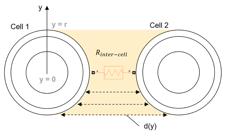
This equation approximates the mean distance between the surfaces of the cylinders:
where L is the closest distance between the cylinders and r is the cell radius, in m.
This example demonstrates how to calculate the thermal resistance between two neighboring cylindrical cells with constant area and no additional intra-cell conduction resistance:
CellsClosestDistance = 0.001; % m
CellHeight = 0.07; % m
CellRadius = 21/2000; % m
InterfaceMaterialConductivity = 0.1; % W/m*K

InterCellThermalResistance = (CellsClosestDistance + CellRadius*(2-pi/2))/(CellRadius*2*CellHeight*InterfaceMaterialConductivity)
disp(InterCellThermalResistance) % K/W
37.4601
buildBattery function or the
Battery Builder app.
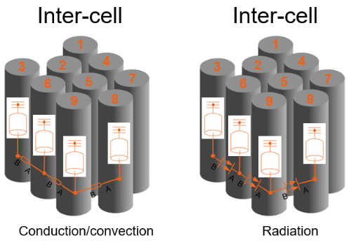
This figure shows the thermal resistors that connect each cell in square and hexagonal
topologies. The figure shows a subset of four cells of a ParallelAssembly
object as an example. In the square topology, the software connects all cell neighbors. In the
hexagonal topology, the software does not directly connect cell 1 with cell 4 because it
considers them too far apart geometrically.
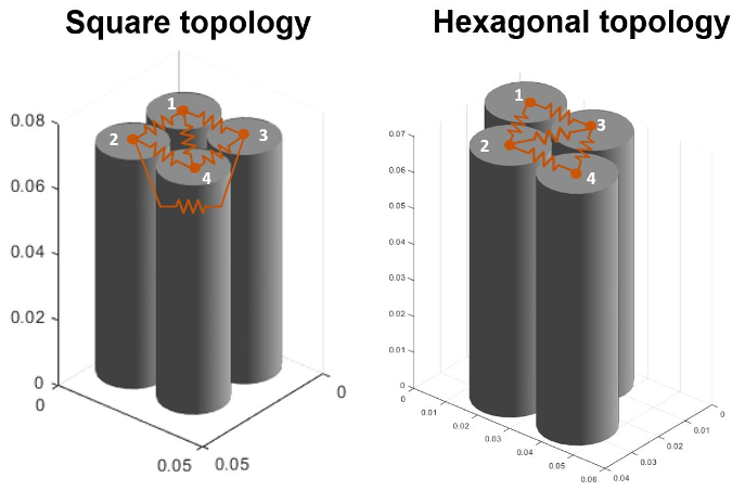
For the square topology, the connections between cells 1 and 4 and between cells 2 and 3 might model a solid material due to the greater distances separating them. For this reason, you set the thermal resistance between these cells to be greater than the thermal resistance that connects cells 1 and 2 or cells 1 and 3. However, if the connection between cells 1 and 4 only has an air gap, then the thermal resistance represents a linear heat exchange or a lumped version of two thermal resistances. To specifically model convection and air between cells, you must parameterize the lumped thermal resistances and thermal masses inside your system.
By default, when you build this ParallelAssembly object, the thermal
resistance value is 1 K/W. However, this value depends on factors such as
the cell format, geometry, size, and material between the cells. For example, a thermal
resistance value of 1.2 K/W might be reasonable for a larger pouch or
prismatic battery, but too permissive for cylindrical cells. You must parameterize the thermal
resistance value for each application and cell format, geometry, and size by using direct
calculations or with detailed 3-D computational fluid dynamics (CFD) models.
Model Inter-Cell Thermal Resistance for Pouch Cell Batteries
In pouch cell batteries, the space between cells typically contains an adhesive, a potting compound or a compression pad. The coolant thermal path is typically located at the bottom along one of the sides of the cell. Cooling plates are often used in pouch cell batteries with active cooling.
This figure shows an example layout for a pouch cell module.
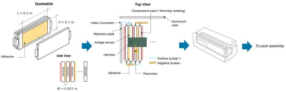
You can calculate the inter-cell thermal resistance values by using the dimensions and material properties of the module constituents.
This example shows how to calculate the thermal resistance between cells for simulation. For pouch cell batteries, cell-to-cell thermal resistance values in the range of 0.01 to 10 K/W are typical.
InterfaceLength = 0.3; % m
InterfaceHeight = 0.1; % m
InterfaceThickness = 0.001; % m
InterfaceMaterialConductivity = 0.1; % W/m*K

InterCellThermalResistance = InterfaceThickness/(InterfaceLength*InterfaceHeight*InterfaceMaterialConductivity)

disp(InterCellThermalResistance) % K/W
0.3333
To learn how to create a battery object with inter-cell heat exchange, see the Build Model of Battery Module with Inter-Cell Heat Exchange example.