Model Linear Resistor in Simscape Language
Let us discuss how modeling in Simscape™ language works, using a linear resistor as an example.
A linear resistor is a simple electrical component, described by the following equation:
where
V | Voltage across the resistor |
I | Current through the resistor |
R | Resistance |
A Simscape file that implements such a linear resistor might look as follows:
component my_resistor
% Linear Resistor
% The voltage-current (V-I) relationship for a linear resistor is V=I*R,
% where R is the constant resistance in ohms.
%
% The positive and negative terminals of the resistor are denoted by the
% + and - signs respectively.

  nodes
    p = foundation.electrical.electrical; % +:left
    n = foundation.electrical.electrical; % -:right
  end
  variables
    i = { 0, 'A' };     % Current
    v = { 0, 'V' };     % Voltage
  end
  parameters
    R = { 1, 'Ohm' };   % Resistance
  end

  branches
    i : p.i -> n.i;
  end

  equations
    assert(R>0)
    v == p.v - n.v;
    v == i*R;
  end

end
Let us examine the structure of the Simscape file my_resistor.ssc.
The first line indicates that this is a component file, and the component name is
my_resistor.
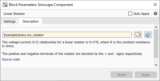
Following this line, there are optional comments that customize the block name and provide
a short description in the block dialog box. Comments start with the %
character.
The next section of the Simscape file is the declaration section. For the linear resistor, it declares:
Two electrical nodes,
pandn(for + and – terminals, respectively).Through and Across variables, current
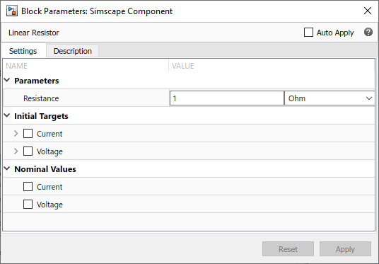
iand voltagev, to be connected to the electrical domain Through and Across variables later in the file. You connect the component and domain variables by specifying the connection between the component variables and nodes.All the public component variables appear on the Variables tab of the dialog box of the block generated from the component file. To specify how the name of the variable appears in the dialog box, use the comment immediately following the variable declaration (
CurrentandVoltage).Parameter
R, with a default value of1 Ohm, specifying the resistance value. This parameter appears in the dialog box of the block generated from the component file, and can be modified when building and simulating a model. The comment immediately following the parameter declaration,Resistance, specifies how the name of the block parameter appears in the dialog box.
The branches section establishes the relationship between the component
Through variable and the component nodes (and therefore the domain Through variable). The
i : p.i -> n.i statement indicates that the current through the
resistor flows from node p to node n.
The final section contains the equations:
The
assertconstruct performs parameter validation, by checking that the resistance value is greater than zero. If the block parameter is set incorrectly, theasserttriggers a run-time error.The first equation,
v == p.v - n.v, establishes the relationship between the component Across variable and the component nodes (and therefore the domain Across variable). It defines the voltage across the resistor as the difference between the node voltages.The second equation,
v == i*R, describes the operation of a linear resistor based on Ohm’s law. It defines the mathematical relationship between the component Through and Across variables, currentiand voltagev, and the parameterR.The
==operand used in these equations specifies continuous mathematical equality between the left- and right-hand side expressions. This means that the equation does not represent assignment but rather a symmetric mathematical relationship between the left- and right-hand operands. This equation is evaluated continuously throughout the simulation.
The following illustration shows the resulting custom block, based on this component file.

To learn more about writing Simscape files and converting your textual components into custom Simscape blocks, refer to the following table.
| For... | See... |
|---|---|
| Declaration semantics, rules, and examples | Declaring Domains and Components |
| Detailed information on writing component equations | Defining Component Equations |
| Annotating the component file to improve the generated block cosmetics and usability | Customizing the Block Name and Appearance |
| Generating Simscape blocks from component files | Generating Custom Blocks from Simscape Component Files |