Main Content

Network Coupler (Flexible Shaft)

Split network at a mechanical rotational connection

Since R2022a

  • Network Coupler (Flexible Shaft) block

Libraries:
Simscape / Utilities / Network Couplers

Description

The Network Coupler (Flexible Shaft) block provides a starting point for you to split a Simscape™ network into two coupled networks at a mechanical rotational connection.

The Network Coupler (Flexible Shaft) block works by adding a compliance between the two networks. It is assumed that there is an inertia on either side of the coupler block. Do not connect the block ports directly to a torque source. You can connect the block ports to an ideal angular velocity source.

If your model has an existing flexible shaft (modeled as a Rotational Spring block connected in parallel with a Rotational Damper block), then use the Network Coupler (Flexible Shaft) block to directly replace these two blocks. This avoids adding a second compliance with which to separate the network. If there is no existing model compliance that you can use, then add a numeric one by inserting the Network Coupler (Flexible Shaft) block at a mechanical rotational connection and setting its Separate using parameter to an added numerical compliance.

Working with the Block on the Model Canvas

When you add the block to your model and double-click it, the Network Coupler (Flexible Shaft) subsystem opens.
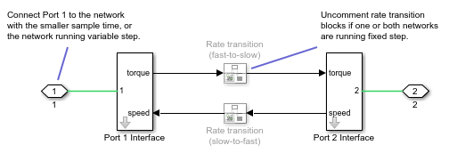
Network Coupler (Flexible Shaft) subsystem diagram

The Port 1 Interface block contains the dynamics that break the algebraic loop. Double-click this block to set all of the Network Coupler (Flexible Shaft) subsystem parameters and view the derived values.

The rate transition blocks are, by default, commented through. Uncomment them if at least one of the coupled networks is running fixed step.

Using the Derived Values to Estimate Block Parameters

On the Analysis tab of the Port 1 Interface block dialog box, the Derived values section contains a list of recommended values that you can use when specifying block parameters. For example, use the Recommended max discrete sample time (s) derived value to verify that your Port 1 network discrete sample time (s) and Port 2 network discrete sample time (s) parameter values are within acceptable limits.

The derived values list is based on the chosen block configuration. For example:

  • If you are using an existing compliance, the block uses information about the inertias of the connected networks, plus the compliance, to recommend either a maximum filter time constant, or a maximum discrete sample time. To do this, the block calculates overall network dynamic time constants and recommends the time constant (Recommended max filter time constant (s)) or sample time (Recommended max discrete sample time (s)) values that are commensurate with the fastest time constant.

  • If you are adding a numeric compliance, the block calculates the stiffness and damping required, based on the connected network inertias and the specified sample time or filter time constant. It also provides an estimate of the fastest trackable time constant. If the Calculated fastest trackable time constant (s) value is too slow for your application, then you must reduce the value you specified for the relevant block parameter, such as Separator time constant (s), Port 1 network discrete sample time (s), or Port 2 network discrete sample time (s).

The Update button lets you recalculate the derived values after you change the parameters of the connected networks.

Examples

Ports

Conserving

expand all

If one of the coupled networks is running variable step, connect it to port 1 of the Network Coupler (Flexible Shaft) block. If both networks are running fixed step, connect this port to the network with the smaller sample time. If both networks are running variable step, or fixed step with the same step size, then the block polarity does not matter.

If one of the coupled networks is running variable step, connect port 2 of the Network Coupler (Flexible Shaft) block to the fixed-step network. If both networks are running fixed step, connect this port to the network with the larger sample time.

Parameters

expand all

Main

Select how to separate the coupled networks:

  • an actual shaft compliance — Split the network at a point where there is an actual flexible shaft. Use the shaft compliance to improve stability of the coupled networks.

  • an added numerical compliance — Add a numerical compliance and use it to improve stability of the coupled networks.

If you are replacing an actual spring and damper in the model, specify the spring rate. Use the Spring rate parameter value from the Rotational Spring block being replaced, converting it to Nm/rad, if necessary.

Dependencies

To enable this parameter, set the Separate using parameter to an actual shaft compliance.

If you are replacing an actual spring and damper in the model, specify the damping coefficient. Use the Damping coefficient parameter value from the Rotational Damper block being replaced, converting it to Nm/(rad/s), if necessary.

Dependencies

To enable this parameter, set the Separate using parameter to an actual shaft compliance.

Select how the coupled networks are sampled:

  • Variable step at ports 1 and 2 — Both networks are variable-step.

  • Variable step at port 1 and fixed step at port 2 — Network 1 is variable-step and Network 2 is fixed-step.

  • Fixed step both ports with common sample time — Both networks are fixed-step, with the same step size.

  • Fixed step both ports with faster sampling at port 1 — Both networks are fixed-step, with different step sizes.

Specify the filter time constant, in seconds, to remove the algebraic loop.

Dependencies

To enable this parameter, set the Sampling type parameter to Variable step at ports 1 and 2.

Specify sample time for Network 1, in seconds.

Dependencies

To enable this parameter, set the Sampling type parameter to Fixed step both ports with common sample time or Fixed step both ports with faster sampling at port 1.

Specify sample time for Network 2, in seconds.

Dependencies

To enable this parameter, set the Sampling type parameter to Variable step at port 1 and fixed step at port 2 or Fixed step both ports with faster sampling at port 1.

Select this check box to enable the prediction (discrete->continuous) algorithm. For more information, see Prediction and Smoothing.

Dependencies

To display this option, set the Sampling type parameter to Variable step at port 1 and fixed step at port 2.

Select this check box to enable the smoothing (continuous->discrete) algorithm. For more information, see Prediction and Smoothing.

Dependencies

To display this option, set the Sampling type parameter to Variable step at port 1 and fixed step at port 2.

Specify time constant, in seconds, for the first-order filter that the smoothing algorithm uses to remove unwanted high-frequency information.

Dependencies

To enable this parameter, select the Use smoothing when connecting variable step to fixed step check box.

Select this check box to enable the prediction (slow->fast) algorithm. For more information, see Prediction and Smoothing.

Dependencies

To display this option, set the Sampling type parameter to Fixed step both ports with faster sampling at port 1.

Select this check box to enable the smoothing (fast->slow) algorithm. For more information, see Prediction and Smoothing.

Dependencies

To display this option, set the Sampling type parameter to Fixed step both ports with faster sampling at port 1.

The smoothing algorithm works by averaging the last N samples. You specify N by using this parameter.

Dependencies

To enable this parameter, select the Use smoothing when connecting fast to slow sample times check box.

Analysis

Specify approximate inertia at port 1, in kg*m^2.

Specify approximate inertia at port 2, in kg*m^2.

For information on how to use the Derived values section, see Using the Derived Values to Estimate Block Parameters.

Initial Conditions

Specify initial condition for the torque transmitted by the shaft, in N*m.

Extended Capabilities

C/C++ Code Generation
Generate C and C++ code using Simulink® Coder™.

Version History

Introduced in R2022a