Network Coupler (Transmission Line)
R2026bNetwork Coupler (Transmission Line) block

To add a block to a model, double-click the canvas and start typing the block name. Then, select the block from the list.
Libraries:
Simscape /
Network Couplers
Description
The Network Coupler (Transmission Line) block provides a starting point for you to split a Simscape™ network into two coupled networks either by splitting an existing transmission line, or by adding a transmission line at the point where you want to separate the networks. Use this block for splitting large power networks consisting of multiple loads, generators, and distribution lines.
The block models the transmission line as a fixed impedance, irrespective of frequency, plus a delay term. The defining equations are
v1( t ) – i1( t ) Z0 = v2( t – τ ) + i2( t – τ ) Z0
v2( t ) – i2( t ) Z0 = v1( t – τ ) + i1( t – τ ) Z0
where:
v1 is the voltage across the left-hand end of the transmission line.
i1 is the current into the left-hand end of the transmission line.
v2 is the voltage across the right-hand end of the transmission line.
i2 is the current into the right-hand end of the transmission line.
τ is the transmission line delay.
Z0 is the line characteristic impedance.
The block models a one-port transmission line that has two physical electrical connections at each end, such as a coaxial cable or twisted pair cable. This block cannot model a three-phase transmission line.
Working with the Block on the Model Canvas
When you add the block to your model and double-click it, the Network Coupler (Transmission Line) subsystem opens.
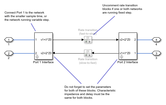
Unlike most of the other coupler blocks, both Port 1 Interface and Port 2 Interface contain the dynamics that break the algebraic loop. Double-click these blocks to set the Network Coupler (Transmission Line) subsystem parameters and view the derived values. You must set the parameters separately for each of the two blocks.
The rate transition blocks are, by default, commented through. Uncomment them if at least one of the coupled networks is running fixed step.
Using the Derived Values to Estimate Block Parameters
The Analysis tab asks you for information about the series resistance and inductance of the connected network and provides advice on the minimum recommended characteristic impedance, to ensure stability.
If the recommended values for the Port 1 Interface and Port 2 Interface blocks are different, select the larger of the two values and apply it to both blocks.
The Update button lets you recalculate the derived values after you change the parameters of the connected networks.
Ports
Conserving
Parameters
Extended Capabilities
Version History
Introduced in R2026b

