Pipe (2P)
Rigid conduit for fluid flow in two-phase fluid systems

Libraries:
Simscape /
Foundation Library /
Two-Phase Fluid /
Elements
Description
The Pipe (2P) block models the flow dynamics of a two-phase fluid inside a rigid pipe. The dynamic compressibility and thermal capacity of the fluid are assumed non-negligible. The two-phase fluid conserving ports A and B represent the pipe inlets. The thermal conserving port H represents the pipe wall, through which heat transfer with the pipe surroundings occurs.
Fluid Inertia
The block provides an option to model fluid inertia, the resistance to sudden changes in mass flow rate. By default, fluid inertia modeling is turned off. This setting is appropriate when the pressure forces driving the flow far exceed the inertial forces acting on the flow.
The default setting reduces computational costs and is recommended for most models. However, fluid inertia can become important if the mass flow rate changes rapidly. In such cases, turning fluid inertia modeling on can help improve simulation accuracy.
Energy Balance
Energy conservation in the pipe is observed through the equation:
where:
M is the fluid mass inside the pipe.
uI is the specific internal energy of the fluid inside the pipe.
ϕA is the energy flow rate into the pipe through port A.
ϕB is the energy flow rate into the pipe through port B.
QH is the heat flow rate into the pipe through the pipe wall, represented by port H.
Heat transfer between the pipe wall and the internal fluid volume is modeled as a convective process, with the heat flow rate computed as:
where:
hcoeff is the average heat transfer coefficient in the pipe.
SSurf is the pipe surface area.
TH is the pipe wall temperature.
TI is the temperature of the fluid in the pipe.
The calculation of the heat transfer coefficient depends on the fluid phase. In the subcooled liquid and superheated vapor phases, the coefficient is:
where the asterisk denotes a value specific to the phase considered (liquid or vapor) and:
Nuis the average Nusselt number in the pipe.kI is the average thermal conductivity in the pipe.Dh is the hydraulic diameter of the pipe (that which a cross section of general shape would have if it were made circular).
In a two-phase mixture, the same coefficient is:
where the subscript M denotes a value specific to
the two-phase mixture and the SL subscript indicates a value obtained
for the saturated liquid.
In laminar flows, the Nusselt number is assumed constant and equal to the value specified in the block dialog box. The laminar flow Nusselt number applies when the Reynolds number is smaller than the value entered for the Laminar flow upper Reynolds number limit parameter.
The turbulent flow Nusselt number applies when the Reynolds number is greater than the value entered for the Laminar flow upper Reynolds number limit parameter. In the transitional region between laminar and turbulent flow, a cubic polynomial function blends the two Nusselt numbers. This blending ensures a smooth transition between flow regimes.
In the liquid and vapor phases, the Nusselt number for turbulent flow follows from the Gnielinski correlation:
where, as before, the asterisk denotes the phase considered and:
f is the friction factor of the pipe.
Reis the Reynolds number.PrI is the Prandtl number.
The friction factor is calculated as:
where εr is the roughness of the pipe. The Reynolds number is calculated as:
where the subscript Avg denotes an average value
between the ports and:
S is the cross-sectional area of the pipe.
vI is the specific volume.
νI is the kinematic viscosity.
In the two-phase mixture, the Nusselt number for turbulent flow follows from the Cavallini and Zecchin correlation:
where the subscript SL denotes a value for saturated
liquid, the SV subscript a value for saturated vapor, and:
xI is the vapor quality.
v is the specific volume.
The Reynolds number of the saturated liquid is calculated as:
Mass Balance
Mass conservation in the pipe is observed through the equation:
where:
ρ is the fluid density.
pI is the pressure inside the pipe.
V is the volume of fluid in the pipe.
is the mass flow rate into the pipe through port A.
is the mass flow rate into the pipe through port B.
∊M is a correction term that accounts for the smoothing of the density partial derivatives across phase transition boundaries.
The block blends the density partial derivatives of the various domains using a cubic polynomial function. At a vapor quality of 0–0.1, this function blends the derivatives of the subcooled liquid and two-phase mixture domains. At a vapor quality of 0.9–1, it blends those of the two-phase mixture and superheated vapor domains. The correction term in the mass conservation equation,
is added to correct for the numerical errors introduced by the cubic polynomial function, with:
M as the fluid mass in the pipe, computed from the equation:
vI as the specific volume of the fluid in the pipe.
τ as the phase-change time constant—the characteristic duration of a phase-change event. This constant ensures that phase changes do not occur instantaneously, effectively introducing a time lag whenever they occur.
Momentum Balance
The momentum balance equations are defined separately for each half pipe section. In the half pipe adjacent to port A:
where:
pA is the pressure at port A.
S is the cross-sectional area of the pipe.
νA is the specific volume of the fluid at port A.
Fvisc,A is the viscous friction force in the half pipe adjacent to port A.
IA is the fluid inertia at port A:
The parameter L is the pipe length.
In the half pipe adjacent to port B:
where:
pB is the pressure at port B.
νB is the specific volume of the fluid at port B.
Fvisc,B is the viscous friction force in the half pipe adjacent to port B.
IB is the fluid inertia at port B:
The fluid inertia terms, IA and IB, are zero when the Enable fluid inertia check box is cleared, that is, when fluid inertia modeling is off. The calculation of the viscous friction forces, Fvisc,A and Fvisc,B depends on the flow regime, laminar or turbulent.
In the laminar regime—that is, when the Reynolds number is smaller than the Laminar flow upper Reynolds number limit value specified in the block dialog box—the viscous friction force in the half pipe adjacent to port A is
while in the half pipe adjacent to port B it is
where:
fshape is the pipe shape factor.
Leff is the effective pipe length—the sum of the pipe length and the aggregate equivalent length of local resistances.
Dh is the hydraulic diameter of the pipe.
In the turbulent regime—that is, when the Reynolds number is greater than the Turbulent flow lower Reynolds number limit value specified in the block dialog box—the viscous friction force in the half pipe adjacent to port A is
while in the half pipe adjacent to port B it is
where:
fA is the Darcy friction factor for turbulent flow in the half pipe adjacent to port A.
fB is the Darcy friction factor for turbulent flow in the half pipe adjacent to port B.
The Darcy friction factor for turbulent flow in the half pipe adjacent to port A follows from the Haaland equation as
and in the half pipe adjacent to port B as
where:
∊r is the relative roughness of the pipe.
ReA is the Reynolds number in the half pipe adjacent to port A,
ReB is the Reynolds number in the half pipe adjacent to port B,
A cubic polynomial function is used to blend the friction losses in the transition region between laminar flow and turbulent flow.
Assumptions and Limitations
The pipe wall is rigid.
The flow is fully developed.
The effect of gravity is negligible.
Heat transfer is calculated with respect to the temperature of the fluid volume in the pipe. To model temperature gradient due to heat transfer along a long pipe, connect multiple Pipe (2P) blocks in series.
Examples
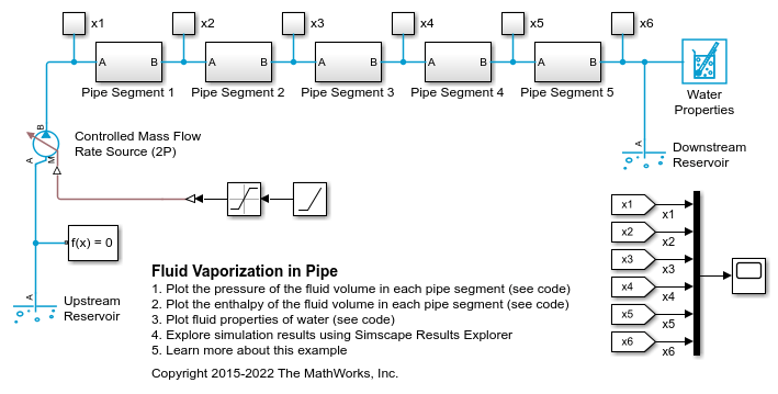
Fluid Vaporization in Pipe
Model the vaporization of water to generate steam. Liquid water enters the pipe at 370 K at a rate of 1 kg/s. The pipe is heated to 1000 K, causing the water flowing inside pipe to saturate.
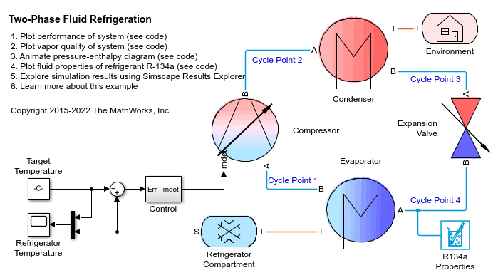
Two-Phase Fluid Refrigeration
Models a vapor-compression refrigeration cycle using two-phase fluid components. The compressor drives the R-134a refrigerant through a condenser, an expansion valve, and an evaporator. The hot gas leaving the compressor condenses in the condenser via heat transfer to the environment. The pressure drops as the refrigerant passes through the expansion valve. The drop in pressure lowers the saturation temperature of the refrigerant. This enables it to boil in the evaporator as it absorbs heat from the refrigerator compartment. The refrigerant then returns to the compressor to repeat the cycle. The controller turns the compressor on and off to maintain the refrigerator compartment temperature within a band around the desired temperature.
Ports
Conserving
Parameters
References
[1] White, F. M., Viscous Fluid Flow. McGraw-Hill, 1991.
[2] Cengel, Y. A., Heat and Mass Transfer – A Practical Approach. 3rd Ed, Section 8.5. McGraw-Hill, 2007.