Simulink-PS Converter
Convert Simulink input signal into physical signal
Libraries:
Simscape /
Utilities
Description
The Simulink-PS Converter block converts the input Simulink® signal into a physical signal. Use this block to connect Simulink sources or other Simulink blocks to the inputs of a Simscape™ physical network.
Block Icon Display on the Model Canvas
To convey signal conversion while taking up minimal canvas space, the block icon changes dynamically based on whether it is connected to other blocks.
When Block Is... | Block Icon |
---|---|
Unconnected |
|
Connected to other blocks |
|
The block icon also changes based on the value of the Input filtering order parameter, to indicate whether filtering is being applied to the input signal.
Input Filtering Order | Unconnected Block Icon | Connected Block Icon |
---|---|---|
|
|
|
|
|
|
Unit Conversion and Checking
Simscape unit manager automatically handles unit propagation and checking within a physical network and performs the necessary unit conversion operations.
The physical signal at the output port of the Simulink-PS Converter block serves as an input signal for the Simscape physical network that the block is connected to. The physical signal unit must be commensurate with the unit expected by the input port of the destination block, that is, the input port connected to the output port of the Simulink-PS Converter block.
Simulink signal units do not propagate into physical networks. The Input signal unit parameter lets you specify a physical unit for the input signal value, so that the Simscape unit manager can perform the necessary unit conversions and scale the output physical signal accordingly.
Note
If you also specify a physical unit as an attribute of the Simulink signal connected to the input port of the block, the software checks that the two units match. For more information, see Working with Simulink Units.
In other words, the Input signal unit parameter does not determine
the units of the output physical signal, it only provides a scaling value. The output
physical signal unit is inferred from the destination block. The default destination block
units are meter-kilogram-second or MKS (SI). If you leave the Simulink-PS
Converter block unitless, with the Input signal unit
parameter set to 1
, then the block does not apply scaling to the input
signal. If you specify different units, commensurate with the expected default units of the
destination block input, then the unit manager attaches these units to the input Simulink signal value and performs the necessary unit conversion when providing the
signal to the destination block.
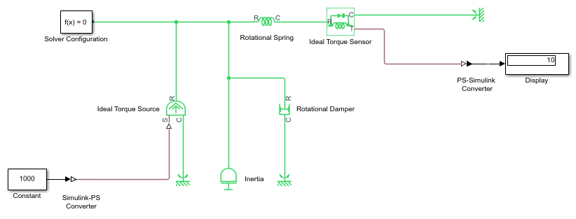
In the diagram below, the Ideal Torque Source block
expects a torque signal, in N*m, on its S port. The
Constant source block provides the value for this input signal. If you left
the Simulink-PS Converter block unitless, the
Ideal Torque Source block would generate torque of 1000
N*m. The parameters of other blocks in this example are chosen so that the output value of
the Ideal Torque Sensor block is equal to the torque
generated by the Ideal Torque Source block, and therefore the
Display block would show the value of 1000. If you change the
Input signal unit parameter value in the Simulink-PS
Converter block to N*cm
, the unit manager performs the
conversion and the Ideal Torque Source block generates torque
of 10 N*m; the torque value in the Display block changes to 10, as shown in
the diagram.
When the input signal is related to thermodynamic variables and contains units of temperature, you must decide whether affine conversion needs to be applied. For more information, see When to Apply Affine Conversion. Usually, if the input signal represents a relative temperature, that is, a change in temperature, you need to apply linear conversion, ΔTnew = L * ΔTold (the default method). However, if the input signal represents an absolute temperature, you need to apply affine conversion, Tnew = L * Told + O.
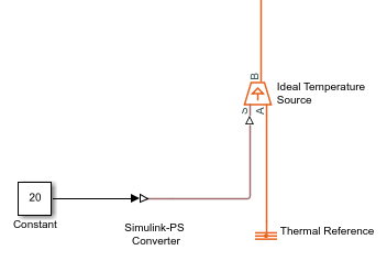
For example, in the Simulink-PS Converter block shown in
the following diagram, if you type degC
in the Input signal
unit field and select the Apply affine conversion check
box, the temperature generated by the Ideal Temperature
Source block is equal to 293.15 K. However, if you leave the
Apply affine conversion check box clear, the output of the
Ideal Temperature Source block is 20 K.
Note
Untyped inputs do not support affine units. If you specify affine units in a Simulink-PS Converter block and then connect it directly to an untyped input port, the signal value is converted to the corresponding fundamental unit and further mathematical operations are performed with that value.
Input Handling
When simulating a model, you may need to provide time derivatives of some of the input signals, especially if you use an explicit solver. One way of providing the necessary input derivatives is by filtering the input through a low-pass filter. Input filtering makes the input signal smoother and generally improves model performance. The additional benefit is that the Simscape engine computes the time derivatives of the filtered input. The first-order filter provides one derivative, while the second-order filter provides the first and second derivatives. If you use input filtering, it is very important to select the appropriate value for the filter time constant.
The filter time constant controls the filtering of the input signal. The filtered input follows the true input but is smoothed, with a lag on the order of the time constant that you choose. Set the time constant to a value no larger than the smallest time interval in the system that interests you. If you choose a very small time constant, the filtered input signal is closer to the true input signal. However, this filtered input signal increases the stiffness of the system and slows the simulation.
Instead of using input filtering, you can provide time derivatives for the input signal directly, as additional Simulink signals. If the provided derivatives are inconsistent with the input signal, then some of the quantities may be incorrect during simulation.
For piecewise-constant signals, you can also explicitly set the input derivatives to zero. Use this option for signals that are truly piecewise-constant, such as step. If you have a continuous input signal sampled with a discrete sample time, setting input derivatives to zero can produce incorrect simulation results. Use one of the other two options: either filter the input or provide time derivatives as separate signals.
Examples
Ports
Input
Output
Parameters
Extended Capabilities
Version History
Introduced in R2007a