Main Content

PEM Fuel Cell System

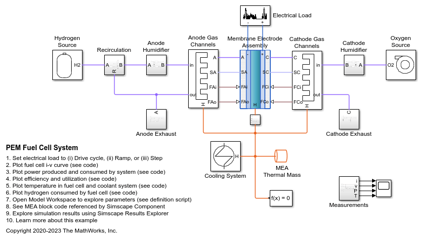
This example shows how to model a proton exchange membrane (PEM) fuel cell stack with a custom Simscape™ block. The PEM fuel cell generates electrical power by consuming hydrogen and oxygen and producing water vapor. The custom block represents the membrane electrode assembly (MEA) and is connected two separate moist air networks: one for the anode gas flow and one for the cathode gas flow.

The two moist air networks represent different gas mixtures. The anode network consists of nitrogen (N2), water vapor (H2O), and hydrogen (H2), representing the fuel. The hydrogen is stored in the fuel tank at 70 MPa. A pressure-reducing valve releases hydrogen to the fuel cell stack at around 0.16 MPa. Unconsumed hydrogen is recirculated back to the stack. The cathode network consists of nitrogen (N2), water vapor (H2O), and oxygen (O2), representing air from the environment. A compressor brings air to the fuel cell stack at a controlled rate to ensure that the fuel cell is not starved of oxygen. A back pressure relief valve maintains a pressure of around 0.16 MPa in the stack and vents the exhaust to the environment.

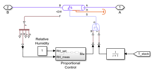
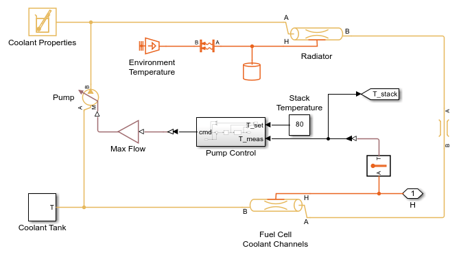
The temperature and relative humidity in the fuel cell stack must be maintained at an optimal level to ensure efficient operation under various loading conditions. Higher temperatures increase thermal efficiency but reduce relative humidity, which causes higher membrane resistance. Therefore, in this model, the fuel cell stack temperature is kept at 80 degC. The cooling system circulates coolant between the cells to absorb heat and rejects it to the environment via the radiator. The humidifiers saturate the gas with water vapor to keep the membrane hydrated and minimize electrical resistance.

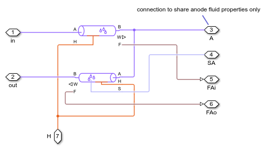
The custom MEA block is implemented in the Simscape code FuelCell.ssc. The output port F of the anode and cathode gas channel pipe blocks provide the gas mole fractions needed to model the fuel cell reaction. The removal of H2 and O2 from the anode and cathode gas flows are implemented by Controlled Trace Gas Source (MA) blocks. The production of H2O and the transport of water vapor across the MEA are implemented by Controlled Moisture Source (MA) blocks. The heat generated by the reaction is sent through the thermal port H to the connected Thermal Mass block. Refer to the comments in the code for additional details on the implementation.

See also the PEM Electrolysis System example.

References:

Dutta, Sandip, Sirivatch Shimpalee, and J. W. Van Zee. "Numerical prediction of mass-exchange between cathode and anode channels in a PEM fuel cell." International Journal of Heat and Mass Transfer 44.11 (2001): 2029-2042.

EG&G Technical Services, Inc. Fuel Cell Handbook (Seventh Edition). US Department of Energy, Office of Fossil Energy, National Energy Technology Laboratory, 2004.

Pukrushpan, Jay T., Anna G. Stefanopoulou, and Huei Peng. Control of fuel cell power systems: principles, modeling, analysis and feedback design. Springer-Verlag London, 2004.

Spiegel, Colleen. PEM fuel cell modeling and simulation using MATLAB. Elsevier, 2008.

Model

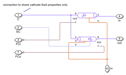
Anode Humidifier Subsystem

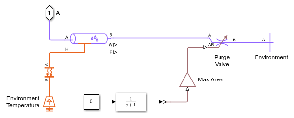
Anode Exhaust Subsystem

Anode Gas Channels Subsystem

Cathode Humidifier Subsystem

Cathode Exhaust Subsystem

Pressure Relief Valve Subsystem

Cathode Gas Channels Subsystem

Cooling System Subsystem

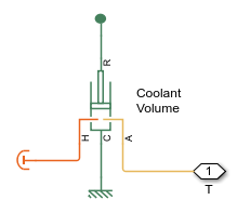
Coolant Tank Subsystem

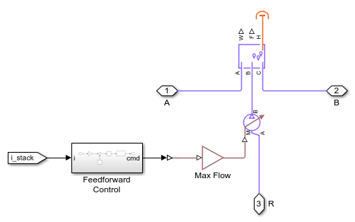
Electrical Load Subsystem

Hydrogen Source Subsystem

Pressure-Reducing Valve Subsystem

Oxygen Source Subsystem

Recirculation Subsystem

Simulation Results from Scopes

Simulation Results from Simscape Logging

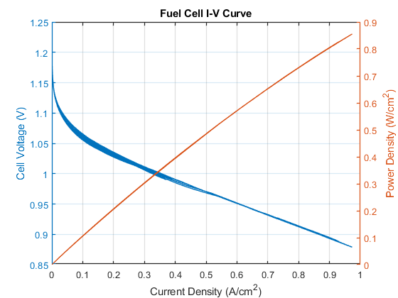
This plot shows the current-voltage (i-v) curve of a fuel cell in the stack. As the current ramps up, an initial drop in voltage occurs due to electrode activation losses, followed by a gradual decrease in voltage due to Ohmic resistances. Near maximum current, a sharp drop in voltage occurs due to gas-transport-related losses.

This plot also shows the power produced by the cell. When the ramp scenario is selected, the power increases until a maximum power output, then decreases due to the high losses near maximum current.

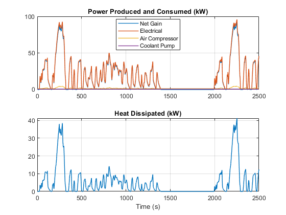
This plot shows the electrical power produced by the fuel cell stack as well as the power consumed by the cathode air compressor and the coolant pump to maintain stable and efficient system operation. As a result, the net power produced by the system is a few percent less than the power produced by the stack. Note that this model assumes an isentropic compressor. Accounting for compressor efficiency would decrease net power gain by another couple of percent.

This plot also shows the excess heat generated by the fuel cell stack, which must be removed by the cooling system. The maximum power produced by the fuel cell stack is 110 kW.

This plot show the thermal efficiency of the fuel cell and its reactant utilization fraction. The thermal efficiency indicates the fraction of the hydrogen fuel's energy that the fuel cell has converted to useful electrical work. The theoretical maximum efficiency for a PEM fuel cell is 83%. However, actual efficiency is around 60% due to internal losses. Near maximum current, the efficiency drops to around 45%.

The reactant utilization is the fraction of the reactants, H2 and O2, flowing into the fuel cell stack that has been consumed by the fuel cell. While higher utilization makes better use of the gases flowing through the fuel cell, it decreases the concentration of the reactants and thus reduces the voltage produced. Unconsumed O2 is vented to the environment, but unconsumed H2 is recirculated back to the anode to avoid waste. However, in practice, the H2 is periodically purged to remove contaminants.

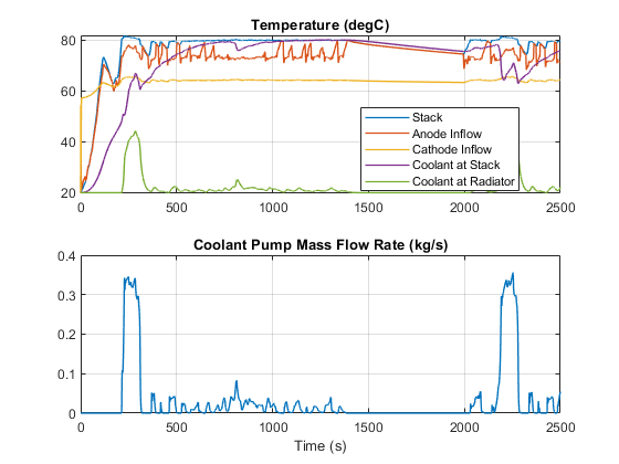
This plot shows the temperatures at various locations in the system. The fuel cell stack temperature is maintained at a maximum of 80 degC by the cooling system. Fuel flowing to the anode is warmed by the recirculated flow. Air flowing to the cathode is warmed by the compressor.

Maintaining an optimal temperature is critical to the operation of the fuel cell because higher temperatures lower the relative humidity which increases the membrane resistance. In this model, the cooling system is operated by a simple control of the coolant pump flow rate. The plot shows the temperature of the coolant after it has absorbed heat from the fuel cell stack and after it has rejected heat in the radiator.

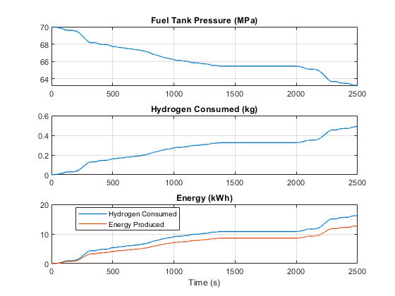
This plot shows the mass of hydrogen used during operation and the corresponding decrease in the hydrogen tank pressure. The energy of the consumed hydrogen fuel is converted to electrical energy.