系统定义和布局
Simulink® 模型的顶层系统布局是许多工程团队可以使用的公共环境,是基于模型的设计范式:分析、设计、检验和实现。您可以通过确定模型的结构和各个组件来定义顶层系统。然后,您可以将模型按照层次结构进行组织,分别与系统的各个组件相对应。接下来,您可以定义每个组件的接口以及组件之间的连接。
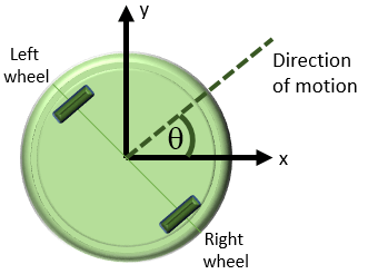
本教程中讨论的模型是一个平板机器人,它可以借助两个轮子进行移动或旋转,类似于家用扫地机器人。此模型假设机器人以下列两种方式之一进行移动:
线性 - 两个轮子以相同的速度向同一方向转动,机器人线性移动。
旋转 - 两个轮子以相同的速度向相反方向转动,机器人原地旋转。

这两种运动都从静止状态开始,也就是说,旋转速度和线性速度均为零。按照这些假设,您可以对线性运动组件和旋转运动组件分别建模。
确定建模目的
在设计模型之前,请明确您的目的和需求。目的决定模型的结构和详细程度。如果目的只是弄清楚机器人可以走多快,那么只对线性运动进行建模就足够了。如果目的是为设备设计一组输入,使它按照给定的路径移动,那就会涉及到旋转组件。如果目的是避障,那么系统就需要一个传感器。本教程的模型构建目的是设计一些传感器参数,使机器人能够在检测到路径中的障碍物时及时停止。要实现此目的,模型必须:
确定电机停止后机器人多长时间能停止下来
提供一系列线性运动和旋转运动的命令,使机器人能够在一个二维空间内移动
第一个建模目的是让您能够分析运动,以便设计传感器。第二个目的是让您能够对设计进行测试。
确定系统组件和接口
明确建模需求之后,即可开始确定系统的组件。确定顶层结构的各个组件及其关系有助于您以系统化方式构建比较复杂的模型。这些步骤是在您构建模型之前在 Simulink 外部进行的。
执行此任务需要回答以下问题:
系统需要哪些结构组件和功能组件?当布局能够反映物理结构和功能结构时,将有助于理解、构建、进行通信和测试系统。当需要在设计过程中的不同阶段实现系统的各个组成部分时,这一点将变得更加重要。
每个组件的输入和输出是什么?绘制一个显示各组件连接情况的图形。此图可帮助您可视化模型中的信号流,确定每个信号的信源和信宿,并确定是否所有必要的组件都存在。
需要达到多高的详细程度?在图中包括主要系统参数。绘制系统图可以帮助您识别并建模对要观察的行为非常重要的部件。实现建模目的所需要的每个组件和参数在模型中都要有一个对应的表示,但需要在模型的复杂程度和可读性之间进行权衡。建模可以是一个反复的过程。您可以从具有很少细节的简要模型开始,然后根据需要逐渐提高复杂程度。
思考以下问题通常也很有帮助:
系统的哪些组成部分需要测试?
测试数据和成功的标准是什么?
哪些输出是分析和设计任务所必需的?
确定机器人运动组件
本教程中的系统定义了一个机器人,它通过两个电动轮子在两个维度上移动。其中包括:
线性运动特性
旋转运动特性
用于确定系统在两个维度上的位置的变换
用于测量机器人与障碍物之间的距离的传感器

此系统的模型包括两个相同的轮子、施加在轮子上的输入作用力、旋转动态特性、坐标变换和一个传感器。此模型使用 Subsystem 表示每个组件:
打开一个新的 Simulink 模型。请参阅打开新模型。
打开库浏览器。请参阅打开 Simulink库浏览器。
添加 Subsystem 模块。将五个 Subsystem 模块从 Ports & Subsystems 库拖放到新模型中。
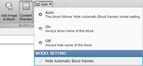
点击一个子系统。在格式选项卡中,点击自动下拉列表。清除隐藏自动模块名称复选框。

按如下所示放置并重命名这五个 Subsystem 模块。要更改模块名称,请双击模块名称并编辑文本。

定义组件之间的接口
确定子系统之间的输入和输出连接。输入和输出值在仿真过程中动态变化。模块之间的连接线代表数据传输。下表显示每个组件的输入和输出。
| 模块 | 输入 | 输出 | 相关信息 |
|---|---|---|---|
| 输入 | 无 | 右轮作用力 左轮作用力 | 不适用 |
| 右轮 | 右轮作用力 | 右轮速度 | 有方向性,负值表示相反方向 |
| 左轮 | 左轮作用力 | 左轮速度 | 有方向性,负值表示相反方向 |
| 旋转 | 左右轮之间的速度差 | 旋转角度 | 逆时针测量 |
| 坐标变换 | 正常速度 旋转角度 | X 速度 Y 速度 | 不适用 |
| 传感器 | X 坐标 Y 坐标 | 无 | 建模不需要任何模块。 |
一些模块输入与模块输出并不完全匹配。因此,除了各个组件的动态特性之外,模型还必须计算以下内容:
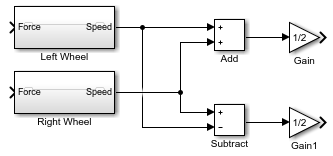
旋转计算的输入 - 两个轮子的速度相减并除以 2。
坐标变换的输入 - 两个轮子的平均速度。
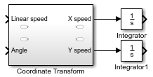
传感器的输入 - 对坐标变换的输出进行积分。
轮子的速度大小始终相等,并且计算在该假设内是精确的。
添加必要的组件并完成连接:
为每个子系统添加必要的输入端口和输出端口。双击 Subsystem 模块。

每个新的 Subsystem 模块都包含一个 Inport (In1) 和一个 Outport (Out1) 模块。这些模块定义信号与模型层次结构中下一个更高层级进行交互的接口。
每个 Inport 模块在 Subsystem 模块上创建一个输入端口,每个 Outport 模块创建一个输出端口。模型通过输入/输出端口名称反映这些模块的名称。为更多的输入和输出信号添加更多模块。在 Simulink 编辑器工具栏上,点击向上导航到父级按钮
 返回顶层。
返回顶层。 对于每个模块,添加并重命名 Inport 和 Outport 模块。

在复制 Inport 模块以创建新模块时,请使用粘贴 (Ctrl+V) 选项。
根据左轮和右轮速度计算 Coordinate Transform 和 Rotation 子系统所需的输入。
计算 Coordinate Transform 子系统的线性速度输入。从 Math Operations 库中添加一个 Add 模块,并将两个轮子组件的输出连接起来。添加一个 Gain 模块,并将 Gain 参数设置为
1/2。将 Add 模块的输出连接到此 Gain 模块。计算 Rotation 子系统的速度差输入。从 Math Operations 库中添加一个 Subtract 模块。将右轮速度连接到 + 输入,将左轮速度连接到 - 输入。连接两个轮子组件的输出。添加一个 Gain 模块,并将 Gain 参数设置为
1/2。将 Subtract 模块的输出连接到此 Gain 模块。
根据 X 速度和 Y 速度计算 X 坐标和 Y 坐标。从 Continuous 库中添加两个 Integrator 模块,并连接 Coordinate Transform 模块的输出。将 Integrator 模块的初始条件设置保留为
0。
完成系统连接。

参数和数据
确定模型需要的参数以及参数的值。根据建模目的决定这些值是始终固定,还是针对不同的仿真而更改。实现建模目的所需要的参数必须在模型中显式表示。下表可以帮助您确定对每个组件进行建模时的详细程度。
| 参数 | 模块 | 符号 | 值 | 类型 |
|---|---|---|---|---|
| 质量 | 左轮 右轮 | m | 2.5 kg | 可变 |
| 滚阻 | 左轮 右轮 | k_drag | 30 Ns2/m | 可变 |
| 机器人半径 | 旋转 | r | 0.15 m | 可变 |
| 初始角 | 旋转 | 无 | 0 rad | 固定 |
| 初始速度 | 左轮 右轮 | 无 | 0 m/s 0 m/s | 固定 |
| 初始 (X, Y) 坐标 | 积分器 | 无 | (0, 0) m | 固定 |
Simulink 使用 MATLAB® 工作区来计算参数。可在 MATLAB 命令行窗口中设置这些参数:
m = 2.5;
k_drag = 30;
r = 0.15;