Modeling
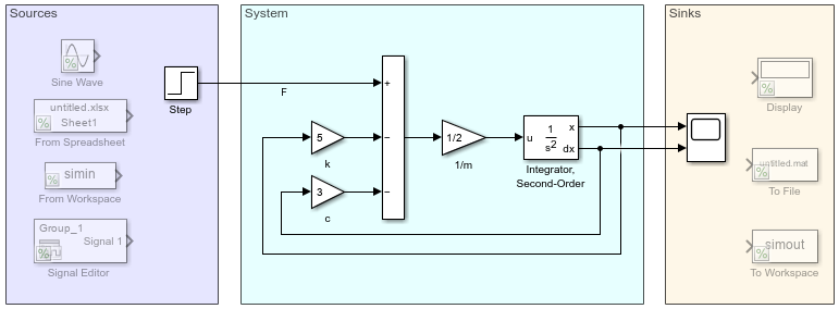
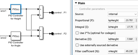
Use Simulink® to model algorithms and physical systems using block diagrams. You can model linear and nonlinear systems, factoring in real-world phenomena such as friction, gear slippage, and hard stops.
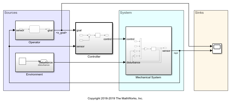
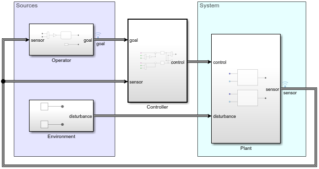
You can design your models to be hierarchical by organizing groups of blocks into subsystems. This approach enables you to build discrete components that reflect your real-life system and simulate the interaction of those components.
Considering system design requirements early can reduce the number of errors found later in the design process. For an example of iterative design, see Basic Modeling Workflow.
Use Simulink for Model-Based Design, where a system model is at the center of the development process, from requirements development, through design, implementation, and testing.
Categories
- Design Model Architecture
Create independent components to share between models or teams, reduce visual complexity with model hierarchy
- Manage Design Data
Choose how to store, partition, and share model design data for small projects and complex model hierarchies
- Design Model Behavior
Modeling techniques for specific functionality and applications
- Configure Signals, States, and Parameters
Configure block parameters, signal ranges, initial states, data types, sample time
- Configure Inputs and Visualizations
Provide signal data and decide how to visualize its simulation
- Analyze and Remodel Design
Assess design completeness and model behavior
- Test Model Components
Manage component test data, execute test suite in SIL or PIL simulation, configure Model Verification blocks, generate options file for Polyspace® analysis
- Modeling Guidelines
Application-specific guidelines for model architecture, design, and configuration
- Tool Qualification and Certification
Qualify Simulink by using the IEC Certification Kit or DO Qualification Kit