FMU
在模型中包含功能模型单元(FMU)
库:
Simulink Extras /
FMU Import
描述
FMU 模块将现有的功能模型单元 (FMU) 导入到 Simulink® 中。该模块会根据您要导入的现有 FMU 自动选择 FMU 模式:
联合仿真 - 集成实现功能模型接口 (FMI) 联合仿真接口的 FMU。这些 FMU 可能包含用于工具耦合的本地求解器。
模型交换 - 集成实现 FMI 模型交换接口的 FMU。这些 FMU 不包含局部求解器,相反,它们从 Simulink 继承了求解器。
该模块支持 FMI 版本 1.0、2.0 和 3.0。对于 FMI 版本 2.0 和 3.0,如果您的 FMU 同时包含联合仿真和模型交换元素,则该模块会检测它们并提示您选择希望该模块运行的模式。
要使用此模块,您必须首先有一个现有的 FMU,从另一个工具导出,或用 C 语言编写。
示例
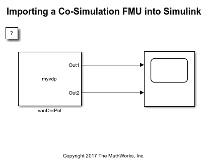
将联合仿真 FMU 导入 Simulink
此示例显示如何使用 FMU Import 模块来加载 FMU 文件。FMU 文件支持在联合仿真模式下执行。Simulink® 软件支持向前和向后步进、调整参数以及保存 FMU Import 模块的状态(只要 FMU 本身支持这些功能)。
端口
输出
占位符端口不产生任何输出。当实际的 FMU 导入到模块时,会配置输入和输出端口。输入和输出端口都支持数值和字符串数据类型。
参数
指定 FMU 的名称,带或不带文件扩展名。此输入区分大小写。FMU 必须存在于 MATLAB® 路径上。
要指定 FMU 名称,请在 FMU 名称文本框中输入名称。
当您点击确定时,该模块会创建一个 /slprj/_fmu/unique_ID 文件夹,其中包含解压的文件和完整的文件层次结构。
依赖关系
指定 FMU 名称时,模块对话框将更新为包含四个选项卡:
参数
仿真
输入
输出
编程用法
模块参数:FMUName |
| 类型:字符向量 |
| 值: FMU 的名称,带或不带文件扩展名 |
默认值:' ' |
参数
此选项卡列出了 FMU 中定义的参数。
要仅显示您感兴趣的参数,请在筛选器字段中输入搜索字符串。该字符串可以与参数名称或描述中的文本匹配。
在参数表中,您可以在值字段中更改参数的值。
导入的参数名称最多为 55 个字符。
您可以通过使用 set_param 函数设置 FMUParamMapping 模块参数来更改结构化模型参数的层次结构。该模块参数可以设置为 Inherit,Flat 或 Structured。默认设置为 Inherit。将其设置为 Flat 可将结构化模型参数分离为具有相应参数名称和值的单独参数。将其设置为 Structured 将模型参数组合成参数值的结构。
输入
此选项卡列出了 FMU modelDescription.xml 中指定的输入变量。
指定结构化输入端口的变量。
要按名称筛选变量,请在文本框中键入变量名称。
变量表列出了层次结构顶部节点及其子节点的变量及其值,您可以在此选项卡上编辑其中的许多变量。
名称 - 变量名称。这是不可编辑的。
可见性 - 选中此复选框可为变量模块上的输入端口。清除此复选框可删除端口。
在顶级节点上选中此复选框可使子节点显示为该模块的一个端口。
注意
当您点击应用时,模块端口的数量会发生变化。请记住相应地添加或删除连接。
开始 - 添加在
modelDescription.xml中定义的开始值。您不能:当相应的输入端口可见时更改值。
向非叶节点添加值。(您只能编辑叶节点的值。)
总线对象名称 - 设置与端口对应的总线对象变量。默认情况下,该变量使用
modelDescription.xml中定义的结构化变量名。要在工作区中创建新变量,请使用fmudialog.createBusType。
更改任何变量值都会启用将输出恢复为默认设置按钮,您可以点击该按钮来恢复原始设置。
您可以通过使用 set_param 函数设置 FMUInputMapping 参数来更改 FMU 模块的输入端口的布局。该参数可以设置为 Inherit、Flat 或 Structured。默认设置为 Inherit。将参数设置为 Flat 可将总线输入端口分成单独的总线元素信号输入端口。将参数设置为 Structured 会将各个总线元素输入端口组合成一个总线输入端口。
输出
此选项卡列出了 FMU modelDescription.xml 中指定的输出变量和内部变量。
指定结构化输出端口的变量。
要按名称筛选变量,请在文本框中键入变量名称。
变量表列出了层次结构顶部节点及其子节点的变量及其值,您可以在此选项卡上编辑其中的许多变量。
名称 - 变量名称。这是不可编辑的。
可见性 - 选中此复选框可为变量模块上的输出端口。清除此复选框可删除端口。如果此 FMU 中存在内部变量,则可以启用或禁用各个内部变量的可见性。如果选择了内部变量,它会创建一个额外的输出端口。
在顶级节点上选中此复选框可使子节点显示为该模块的一个端口。
注意
当您点击应用时,模块端口的数量会发生变化。请记住相应地添加或删除连接。
开始 - 添加在
modelDescription.xml中定义的开始值。您不能更改或添加输出变量的值。总线对象名称 - 设置与端口对应的总线对象变量。默认情况下,该变量使用
modelDescription.xml中定义的结构化变量名。要在工作区中创建新变量,请使用fmudialog.createBusType。
更改任何变量值都会启用将输出恢复为默认设置按钮,您可以点击该按钮来恢复原始设置。
您可以通过使用 set_param 函数设置 FMUOutputMapping 参数来更改 FMU 模块的输出端口的布局。该参数可以设置为 Inherit、Flat 或 Structured。默认设置为 Inherit。将参数设置为 Flat 可将总线输出端口分成单独的总线元素信号输出端口。将参数设置为 Structured 会将各个总线元素输出端口组合成一个总线输出端口。
仿真
选中此复选框可以指定 FMU 的容值。否则,请清除此复选框。
依赖关系
此参数仅当您的 FMU 版本或模式支持容值时才适用。
编程用法
模块参数:FMUIsToleranceUsed |
| 类型:字符向量 |
| 值: on | off |
默认值:'off' |
FMU 相对容值(%),指定为标量。
依赖关系
此参数仅当您的 FMU 版本或模式支持容值时才适用。
编程用法
模块参数:FMUToleranceValue |
| 类型:字符向量 |
值:1E-3 | 标量 |
默认值:'1E-3' |
选择用于仿真 FMU 的二进制文件。当 FMU 包含 Linux® 二进制文件时,将 Windows® 上的 FMU 的此选项设置为 linux64。
依赖关系
在 Windows 上使用 Linux 二进制文件仿真 FMU 需要安装以下产品:
Simulink Compiler™
FMU Builder for Simulink 支持包
Windows Subsystem for Linux (WSL) 版本 2.0.9.0 或更高版本
有关详细信息,请参阅Simulate FMU with Linux Binary on Windows (Simulink Compiler)。
编程用法
模块参数:FMUSelectedBinary |
| 类型:字符向量 |
值:x86_64-windows | x86-windows | linux64 |
默认值:'win64' |
以事件模式仿真 FMU。
依赖关系
仅当 FMU 支持事件模式时才启用此参数,并且仅当您的 FMU 在联合仿真模式下使用且与 FMI 3.0 标准兼容时才适用。
编程用法
模块参数:CSEventModeEnabled |
| 类型:字符向量 |
| 值: on | off |
默认值:'on' |
要启用 FMU 调试记录的显示,请选中此复选框。否则,请清除此复选框。
编程用法
模块参数:FMUDebugLogging |
| 类型:1xN 字符向量元胞数组 |
| 值: on | off |
默认值:'off' |
按类型筛选调试日志,通过选中以下复选框来指定:
确定
警告
丢弃
错误
致命
待处理
编程用法
模块参数:FMUDebugLoggingFilter |
| 类型:字符向量 |
值:OK | Warning | Discard | Error | Fatal | Pending |
默认值: 'OK' | 'Warning' | 'Discard' | 'Error' | 'Fatal' | 'Pending' |
直接调试日志,指定为:
文件 - 流式传输至
slprj/_fmu/_logs_modelname/modelname_FMUblockname.txt。显示 - 流至 MATLAB 命令行窗口。
依赖关系
将此参数设置为 File 可启用 Open FMU Log File...链接。
编程用法
模块参数:FMUDebugLoggingRedirect |
| 类型:字符向量 |
值:File | Display |
默认值:'File' |
代码生成
为 FMU 模块的生成代码指定 FMI API 的源。说明生成的代码是否使用从源代码内联的 FMU 函数或使用函数指针引用从编译的二进制文件获得的 FMI API。基于源代码的代码生成是嵌套 FMU、ERT 目标、GRT 目标和快速加速仿真模式的默认选项。有关示例,请参阅Integrate FMI APIs in Generated Code Using FMU Source Code or Binary。
提示
将此选项设置为 source code 以使生成的代码能够跨多个平台进行编译。
依赖关系
仅当 FMU 包包含从 Simulink 生成的源代码时,此选项才有效。当您的 FMU 仅包含来自外部工具的二进制文件或源代码时,该选项处于非活动状态,并且代码生成使用已编译的二进制文件。
编程用法
模块参数:FMUCGType |
| 类型:字符向量 |
值:source code | shared library | auto |
模块特性
版本历史记录
在 R2017b 中推出在 Simulink 中导入并仿真包含 Windows 32 位 DLL 的 FMU。为此,在 FMU 模块的 仿真选项卡中,将 仿真 FMU using: 参数设置为 x86-windows。
使用其打包的源代码为从 Simulink 生成的 FMU 生成代码。基于源代码的代码生成是嵌套 FMU、ERT 目标、GRT 目标和快速加速器仿真模式的默认设置。在此之前,FMU 生成的代码依赖于其平台特定的编译二进制文件。
具有恒定周期时钟的独立联合仿真 FMU 模块得到了增强,以提高仿真和性能。您现在可以:
为包含 FMU 的模型生成代码。
在快速加速器模式下使用 FMU 仿真模型。
将 FMU 纳入模型参考并在加速器模式下仿真。
生成嵌套的 FMU。
FMU 导入模块支持导入带有基于时间的时钟的独立联合仿真 FMU。Simulink 将基于时间的 FMU 时钟变量注册为 FMU 模块的采样时间,使该模块能够处理时钟事件更新并与 FMU 同步。
仅在正常模式仿真中支持带时钟的 FMU 仿真。该模块不支持代码生成。
FMU 导入模块支持以下 FMI 3.0 功能:
引入新的整数和浮点数据类型。
对向量和矩阵的原生支持。
事件模式支持联合仿真模式。
二进制数据类型支持。
FMU 导入模块检测模型交换 FMU 的离散输入值变化并触发事件迭代。
FMU 导入模块支持模块输入和输出的枚举数据类型。
MATLAB Command
You clicked a link that corresponds to this MATLAB command:
Run the command by entering it in the MATLAB Command Window. Web browsers do not support MATLAB commands.
选择网站
选择网站以获取翻译的可用内容,以及查看当地活动和优惠。根据您的位置,我们建议您选择:。
您也可以从以下列表中选择网站:
如何获得最佳网站性能
选择中国网站(中文或英文)以获得最佳网站性能。其他 MathWorks 国家/地区网站并未针对您所在位置的访问进行优化。
美洲
- América Latina (Español)
- Canada (English)
- United States (English)
欧洲
- Belgium (English)
- Denmark (English)
- Deutschland (Deutsch)
- España (Español)
- Finland (English)
- France (Français)
- Ireland (English)
- Italia (Italiano)
- Luxembourg (English)
- Netherlands (English)
- Norway (English)
- Österreich (Deutsch)
- Portugal (English)
- Sweden (English)
- Switzerland
- United Kingdom (English)

