实现 FMU 模块
实现一个模块并为其分配一个功能模型单元 (FMU)。然后,您可以浏览该模块以查看 FMU。此示例将 FMU 模块与车辆 FMU 结合使用。
创建一个模型并添加 FMU 模块。
如果您的 FMU 源代码缺失当前平台的二进制文件,您可以使用
fmudialog.compileFMUSources函数为当前平台生成二进制文件。在模块对话框中,在 FMU 名称参数中输入 FMU 文件的路径名称,然后点击确定或应用。文件扩展名
.fmu是可选的。第一次点击确定或应用时,模块会标识要将您的 FMU 设置为哪个 FMU 模式(联合仿真或模型交换)。
模块还会创建一个
slprj/_fmu/fmu_name文件夹,并将 FMU 文件的内容解包到此文件夹中,该文件夹包括(可选):binaries- FMU 二进制文件documentation- FMU 文档 HTML 文件resources- FMU 源文件sources- FMU 源文件其他支持文件,例如模块封装和描述文件
FMU 模块图标和端口标签更新为对应 FMU 的标签。在将模块与 FMU 关联后,如果要更改 FMU,请右键点击 FMU 模块,选择模块参数,然后在 FMU 名称中输入新 FMU 名称。本主题中的相应部分使用Simplify Interface for Structured Data with FMU Import Block示例中的 FMU。
浏览 FMU 模块
双击该模块。假设您点进了当前文件夹中名为 fmuVehicAOB.fmu 的 FMU。FMU 模块对话框会显示在 fmuVehicAOB.fmu 文件中定义的 FMU 参数。
“参数”选项卡
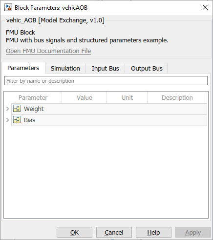
列出 FMU 模块参数。根据需要编辑值。您可以通过展开树视图来编辑结构体参数的元素。
输入和输出总线选项卡
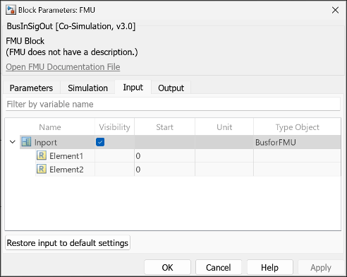
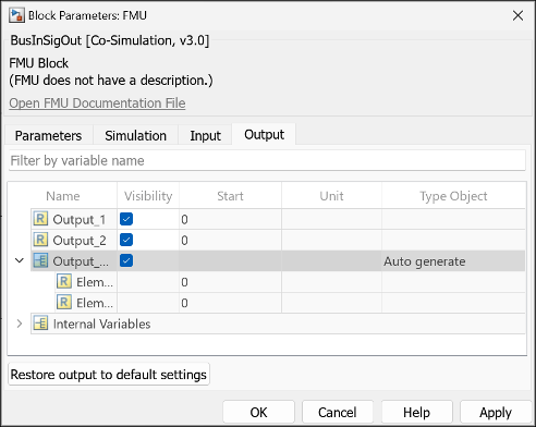
这两个选项卡列出模块定义的输入和输出端口。类型对象字段列出具有总线或枚举类型的端口的总线对象或枚举类。FMU 模块使用 modelDescription.xml 文件中的元数据来确定总线和枚举类型端口的信号属性。
对于枚举类型端口,将输入和输出选项卡中的类型对象字段设置为 Inherit:Auto,以使下游和上游模块能够继承信号数据。
对于总线类型端口,将输出选项卡中的类型对象字段设置为 Auto generate,以使下游模块能够继承信号数据。总线端口不支持后向继承。您需要为具有总线类型输入端口的 FMU 提供兼容的总线类型输入信号。
使用 fmudialog.createBusType 函数在工作区中创建 FMU 使用的总线对象:
fmudialog.createBusType(gcb)
使用 fmudialog.createEnumType 函数在工作区中创建 FMU 使用的枚举类:
fmudialog.createEnumType(gcb)
“仿真”选项卡
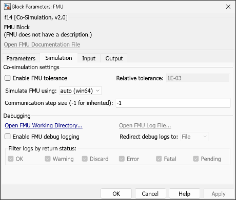
启用与仿真相关联的自定义。
要输入相对容差,请选择启用 FMU 容差并进行设置。
要确定模型中模块的采样时间,请设置通信步长。要从 Simulink® 求解器继承步长,请设置为
-1。仅当 FMU 是联合仿真 FMU 时,此选项才可用。要在事件模式下进行仿真,请选中启用事件模式选项。仅当您的 FMU 用于联合仿真模式并且与 FMI 3.0 标准兼容时,此选项才可用。
要启用日志记录,请选择启用 FMU 调试日志。
在重定向调试日志至中,选择日志的目标位置。
文件,保存到
slprj\_fmu\_logs_modelname\modelname_blockname.txt显示,显示在 MATLAB® 命令行窗口中。
如果选中启用 FMU 调试日志复选框且重定向调试日志至参数设置为
Display,则不能使用 FMU 模块进行联合仿真。有关联合仿真和多个内核的详细信息,请参阅Run Co-Simulation Components on Multiple Cores在按返回状态过滤日志中,选中所需返回状态的对应复选框。
使用 FMU 仿真方式参数指定 FMU 仿真的二进制文件。对于 64 位 Windows 二进制文件,将其指定为 x86_64-windows,对于 32 位 Windows 二进制文件,指定为 x86-windows。如果您在 Windows® 上有具有 Linux® 二进制文件的 FMU,并且要使用 Linux 二进制文件进行仿真,请将 FMU 仿真方式参数设置为 x86_64-linux。有关详细信息,请参阅Simulate FMU with Linux Binary on Windows (Simulink Compiler)。
“代码生成”选项卡

为 FMU 模块的生成代码指定 FMI API 的源。说明生成的代码是使用从源代码内联的 FMU 函数,还是使用函数指针从编译的二进制文件引用 FMI API。基于源代码的代码生成是嵌套 FMU、ERT 目标、GRT 目标和快速加速仿真模式的默认选项。有关示例,请参阅Integrate FMI APIs in Generated Code Using FMU Source Code or Binary。
更改模块输入、输出、参数和内部变量结构体
您可以使用以下参数更改 FMU 模块输入端口、输出端口和参数的布局:
| 参数 | 操作 | 设置 |
|---|---|---|
FMUInputMapping | 更改输入端口的层次结构。 |
|
FMUOutputMapping | 更改输出端口的层次结构。 |
|
FMUParamMapping | 更改参数的层次结构。 |
|
FMUInternalMapping | 更改内部变量的层次结构 |
|
使用 get_param 和 set_param 函数设置这些值。例如,假设某模块参数选项卡具有一个结构体构造:
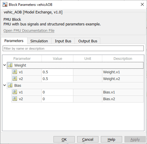
参数包含在 struct 中。要单独列出参数,请将 FMUParamMapping 属性设置为 'Flat':
set_param(gcb,'FMUParamMapping', 'Flat')

计时注意事项
您可以使用通信步长参数设置 FMU 模块的采样时间。与所有 Simulink 模块一样,此模块的采样时间设置 tC 必须是模型采样时间 tM 的整数倍。如果通信步长 tC 不是模型步长 tM 的倍数,则 Simulink 会生成错误。
另一方面,FMU 的局部步长 tL 是 FMU 设定的一部分,仅应用于 FMU 内部。为了正常运行,通信步长 tC 也必须是 tL 的整数倍。如果模型采样时间 tM 或模块采样时间 tC 与 FMU 局部步长 tL 不兼容,则 FMU 是否会在运行时产生错误取决于其具体实现。
FMU 模块支持导入具有时基时钟的 FMU。您可以使用时基时钟 FMU 变量控制 FMU 的执行速度。有关在 Simulink 中仿真具有时基时钟的 FMU 的示例,请参阅Import and Simulate FMU with Time-Based Clocks in Simulink。
FMU 故障排除
如果使用 FMU 时遇到问题,请执行下列操作:
使用 FMU 检查工具验证您的 FMU。
选中 FMU 模块的“仿真”选项卡上的启用 FMU 调试日志复选框。
联系 FMU 供应商。