Import and Simulate FMU with Time-Based Clocks in Simulink
This example demonstrates the use of a Functional Mockup Unit (FMU) containing time-based clocks in Simulink®. You can import standalone co-simulation FMUs that implement the following types of time-based clocks as defined in the FMI 3.0 standard:
Constant periodic clock
Fixed periodic clock
Tunable periodic clock
Changing aperiodic clock
Countdown aperiodic clock
For detailed information about these clocks, see clock definition in the FMI 3.0 standard.
Import FMU into Simulink
Open the clockImportModel model that imports the mixedClocks FMU into Simulink.
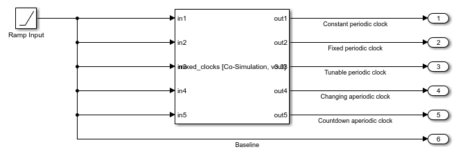
This FMU implements a direct feedthrough operation of the input with a unity gain, ensuring the output is the same and the input at each time step when the FMU is executed. The FMU has five inputs and five output ports, with each corresponding input-output pair configured with a specific time-based clock.
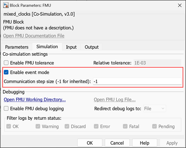
To enable simulation with clock events, on the FMU block dialog, in the Co-simulation settings of the Simulation tab, select the Enable event mode check box and set Communication step size parameter as -1.
Simulate and Observe the FMU Output for a Ramp Input
The model applies an identical ramp signal to each of the inputs of the FMU. Simulate the model.
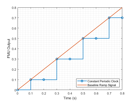
The first input and output ports of the FMU are configured with a constant periodic clock. Constant periodic clocks of FMUs are registered as discrete sample times in Simulink. The ports associated with these clocks execute at a specified period and offset. In this FMU, the clock is configured to set the port period as 0.2 seconds and the offset as 0.1 second. Observe that the FMU output matches the baseline signal only at those specified intervals.
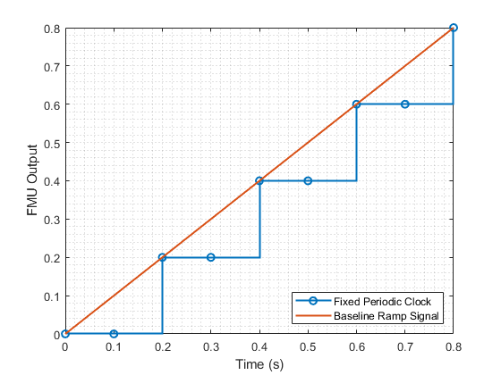
The second input and output ports are configured with a fixed periodic clock. Fixed period clocks of FMUs are registered as variable sample times in Simulink. The ports associated with these clocks execute at a fixed period and offset similar to ports with constant periodic clocks. However, the period and offset are not required to be specified at the time of FMU creation and can be set during initialization. In this FMU, the clock is configured to set the port period as 0.2 seconds and offset as 0 second during initialization. Observe that the FMU output matches the baseline signal only at those specified intervals.
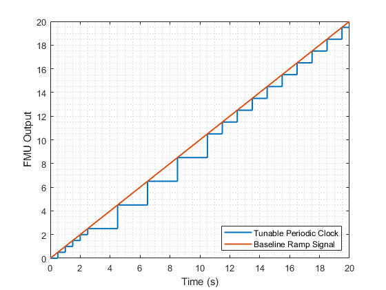
The third input and output ports are configured with a tunable periodic clock. Tunable periodic clocks of FMUs are registered as variable sample times in Simulink. The ports associated with these clocks execute at a fixed period and offset similar to constant and fixed periodic clocks. However, for these clocks the period can be changed during simulation. In this FMU, clock is configured to initially set the port period as 0.5 seconds. The period is changed to 2 seconds in the time step after 2 simulation seconds have elapsed and then changed to 1 second in the time step after 10 simulation seconds have elapsed. Observe the specified change in the period of the FMU output in the simulation result.
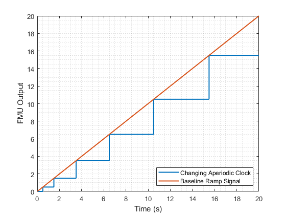
The fourth input and output ports are configured with a changing aperiodic clock. Changing aperiodic clocks of FMUs are registered as variable sample times in Simulink. The interval between successive executions of these ports can be changed at the end of each time step. This enables intervals to be adjust during simulation according to run-time parameters. In this FMU, the clock is configured for the interval to the next execution to increase by 1 second at every execution step. Observe the increasing interval times of the FMU output in the simulation result.
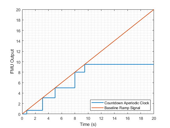
The fifth input and output ports are configured with a countdown aperiodic clock. Countdown aperiodic clocks are registered as variable sample times in Simulink. These clocks do not require the interval to the next execution to be known at the end of the current execution step, enabling execution at arbitrary times. In this FMU implementation, the interval to the next execution is defined only at simulation times 2, 4, 7, and 8.5 seconds. The interval is set as 1 second at each of these time steps and the port executes after an interval of 1 second after each of these time steps are hit.
